Unit 5 - Notes
Unit 5: Introduction to Sequential Logic Circuits
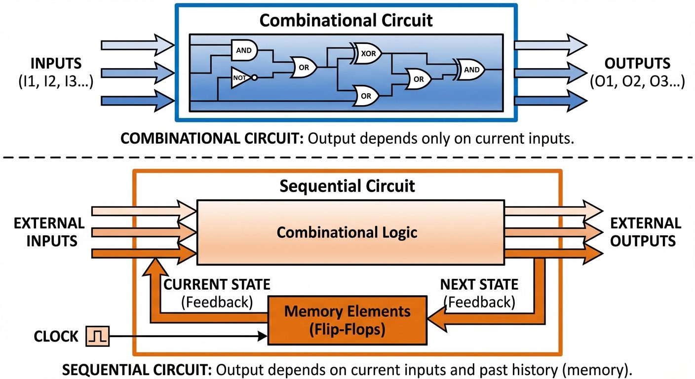
1. Introduction to Sequential Logic
Unlike Combinational Logic circuits, where the output depends solely on the immediate present inputs (e.g., Adders, Encoders), Sequential Logic circuits depend on both the present inputs and the past history of inputs (previous state).
Key Characteristics:
- Memory: They possess memory elements to store binary information.
- Feedback: Output is fed back to the input.
- Clock: Operations are often synchronized using a clock signal.
2. Latches
A Latch is the fundamental building block of sequential circuits. It is a bistable multivibrator, meaning it has two stable states (0 and 1). Latches are level-triggered (they change state as long as the control signal is active).
2.1 SR Latch (Set-Reset)
The SR Latch is the simplest form of storage. It can be constructed using NOR gates or NAND gates.
A. NOR Gate SR Latch (Active High)
- R (Reset): Resets output to 0.
- S (Set): Sets output to 1.
- Feedback: The output of one NOR gate is the input to the other.
Truth Table (Active High):
| S | R | (Next State) | Action |
|---|---|---|---|
| 0 | 0 | Hold (No Change) | |
| 0 | 1 | 0 | Reset |
| 1 | 0 | 1 | Set |
| 1 | 1 | X | Invalid (Forbidden) |
Note: The state is forbidden because it tries to force both outputs to 0, violating the complementary rule ( and ).
B. NAND Gate SR Latch (Active Low)
Ideally operates with inverted inputs ().
- : Invalid.
- : No Change.
2.2 D Latch (Data/Transparent Latch)
To solve the forbidden state of the SR latch and ensure inputs and are never equal simultaneously, the D Latch connects and together using an inverter.
- Input: Single data input .
- Enable (E): When , Output follows Input (). When , the state is latched ( holds previous value).
3. Flip-Flops
A Flip-Flop is a latch with additional control circuitry (Clock). While latches are level-triggered, Flip-Flops are edge-triggered (state changes only on the rising or falling edge of the clock pulse).
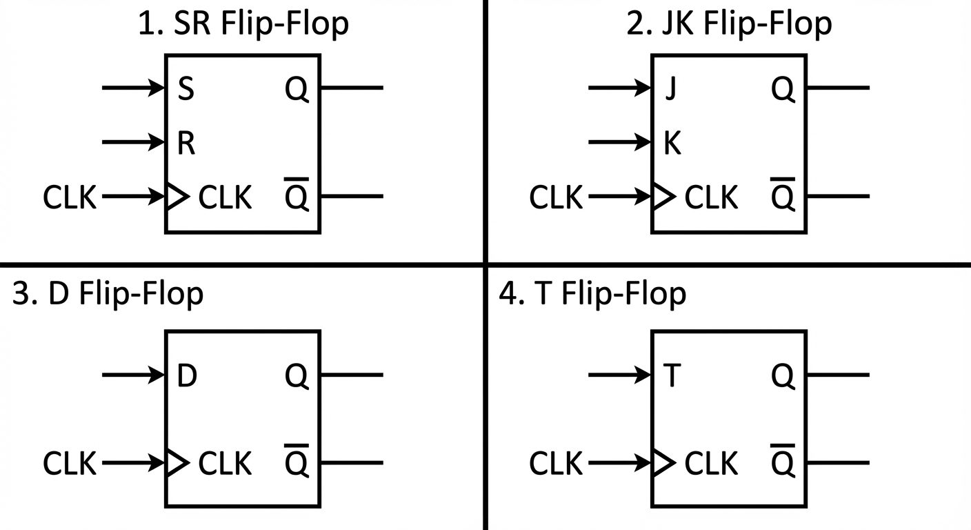
3.1 SR Flip-Flop
Essentially a Gated SR Latch equipped with edge-detection logic.
- Logic:
- If on clock edge Set ().
- If on clock edge Reset ().
- If on clock edge No Change.
- If on clock edge Invalid/Indeterminate.
3.2 JK Flip-Flop
Designed to eliminate the invalid state of the SR Flip-Flop.
- J acts like Set.
- K acts like Reset.
Truth Table:
| CLK | J | K | State | |
|---|---|---|---|---|
| 0 | 0 | No Change | ||
| 0 | 1 | 0 | Reset | |
| 1 | 0 | 1 | Set | |
| 1 | 1 | Toggle |
The Toggle Mode: When and , the output inverts its state on every clock pulse.
Race Around Condition:
In a level-triggered JK flip-flop (or if the clock pulse width is too wide), if , the output will toggle continuously during the high level of the clock. This creates an uncertain output state. Solution: Use Master-Slave JK Flip-Flop.
3.3 D Flip-Flop (Delay Flip-Flop)
Constructed from a JK or SR flip-flop by connecting the inputs via an inverter ( or ).
- Function: Transfers the input to output on the clock edge.
- Use: Data storage, Shift Registers.
- Characteristic Equation:
3.4 T Flip-Flop (Toggle Flip-Flop)
Constructed by connecting J and K inputs together ().
- T=0: No Change ().
- T=1: Toggle ().
- Use: Counters, Frequency Dividers.
- Characteristic Equation:
4. Master-Slave Flip-Flop
The Master-Slave configuration is designed specifically to eliminate the Race Around Condition found in JK Flip-Flops.
Architecture
It consists of two latches/flip-flops cascaded together:
- Master: Receives external inputs. Driven by Clock (CLK).
- Slave: Receives output of the Master. Driven by Inverted Clock ().
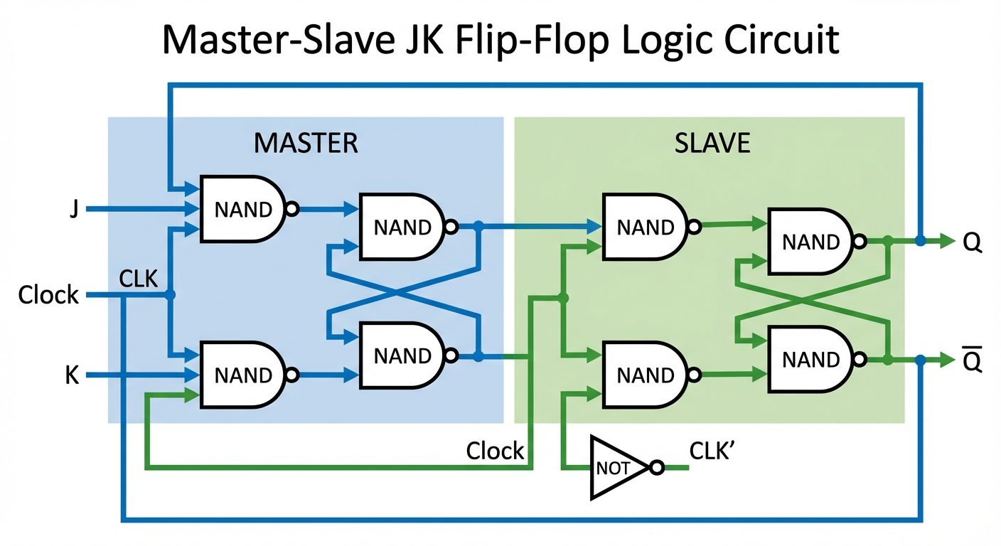
Operation
- When Clock is High (CLK = 1):
- Master is active (Processes J and K inputs).
- Slave is inactive (Isolated from Master).
- Master output settles, but Slave output does not change yet.
- When Clock is Low (CLK = 0):
- Master is inactive (Holds its state).
- Slave is active.
- Slave takes the Master's output and passes it to the final output .
Result: The output changes only once per clock cycle (on the falling edge), preventing continuous toggling.
5. Conversion of Basic Flip-Flops
Flip-flops can be converted from one type to another (e.g., creating a JK functionality using a D flip-flop) using combinational logic.
General Design Steps:
- Identify the Available Flip-Flop (what you physically have) and the Required Flip-Flop (what you want to build).
- Draw the Characteristic Table (Truth Table) for the Required Flip-Flop.
- Add the Excitation Table for the Available Flip-Flop to the columns.
- Derive Boolean expressions for the Available Flip-Flop inputs using K-Maps.
- Draw the final circuit.
Important Reference: Excitation Tables
| S R | J K | D | T | |
|---|---|---|---|---|
| 0 X | 0 X | 0 | 0 | |
| 1 0 | 1 X | 1 | 1 | |
| 0 1 | X 1 | 0 | 1 | |
| X 0 | X 0 | 1 | 0 |
(Where X = Don't Care)
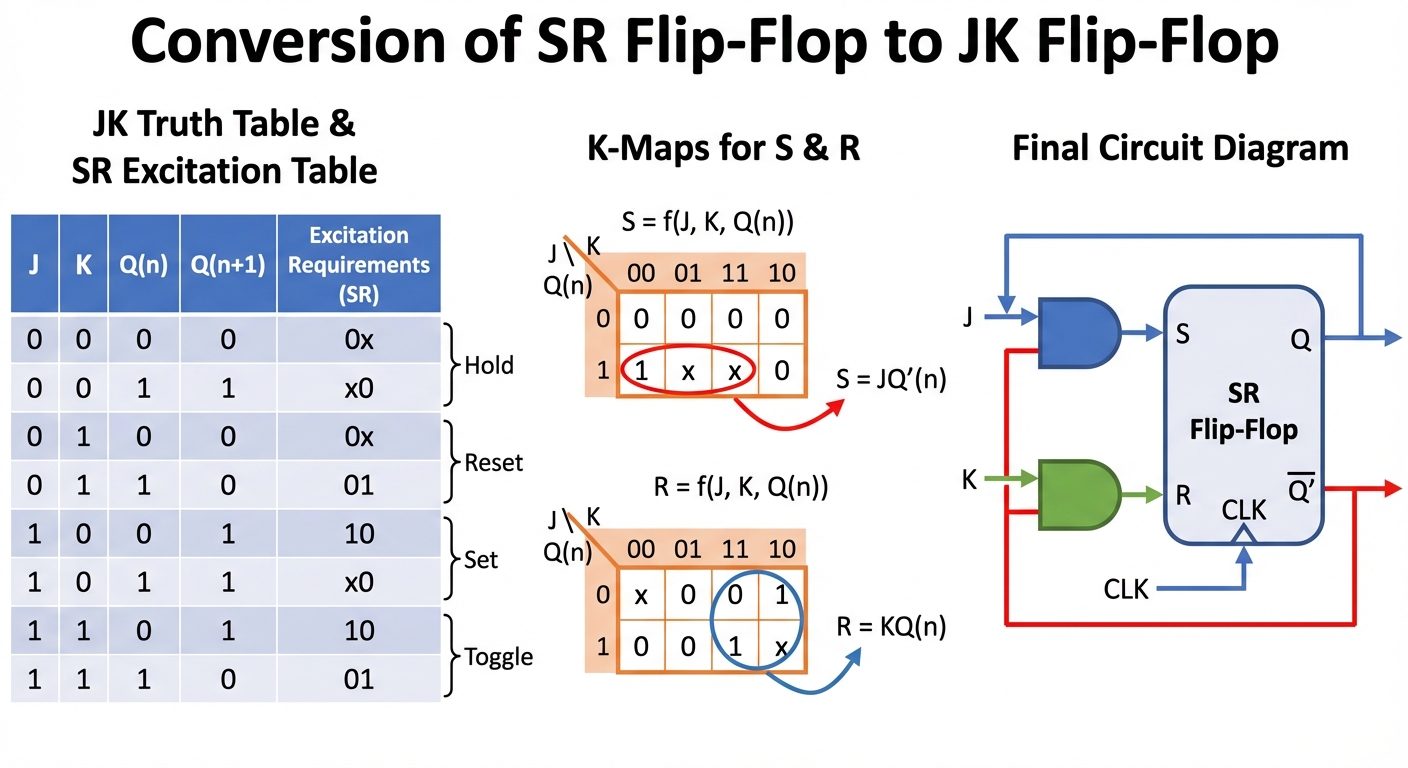
Example: Converting SR to JK Flip-Flop
Objective: Use an SR Flip-Flop to behave like a JK Flip-Flop.
- Truth Table (Required JK functionality):
| J | K | Action | ||
|---|---|---|---|---|
| 0 | 0 | 0 | 0 | Hold |
| 0 | 0 | 1 | 1 | Hold |
| 0 | 1 | 0 | 0 | Reset |
| 0 | 1 | 1 | 0 | Reset |
| 1 | 0 | 0 | 1 | Set |
| 1 | 0 | 1 | 1 | Set |
| 1 | 1 | 0 | 1 | Toggle |
| 1 | 1 | 1 | 0 | Toggle |
-
Map to Available SR Inputs:
Using the SR Excitation table, determine what S and R values are needed to achieve the transition. -
K-Map Simplification:
- For Input S: Grouping yields
- For Input R: Grouping yields
-
Logic Diagram:
- Connect two AND gates to the inputs of the SR Flip-Flop.
- Input S receives .
- Input R receives .