Unit 6 - Notes
Unit 6: Applications of Sequential Circuits
1. Shift Registers
A register is a set of flip-flops (FFs) capable of storing binary data. Since a single flip-flop stores one bit, an -bit register requires flip-flops. A Shift Register is a register capable of shifting the binary information held within its cells to neighboring cells upon the application of a clock pulse.
1.1 Operation and Types
Shift registers are categorized by the method of data entry (Serial or Parallel) and data retrieval (Serial or Parallel).
A. Serial-In Serial-Out (SISO)
- Data Entry: Serial (one bit at a time).
- Data Output: Serial (one bit at a time).
- Operation:
- Consists of cascaded D flip-flops.
- The output of one FF is connected to the input of the next.
- Data shifts one position to the right (or left) for each clock pulse.
- Latency: To store bits, it takes clock cycles. To read them out, it takes another cycles (total to utilize data fully).
- Application: Time delay circuits, serial communication buffers.
B. Serial-In Parallel-Out (SIPO)
- Data Entry: Serial.
- Data Output: Parallel (all bits available simultaneously).
- Operation:
- Data enters serially like SISO.
- The output of each flip-flop is accessible simultaneously via parallel output lines.
- Application: Serial-to-Parallel conversion (e.g., receiving data from a modem).
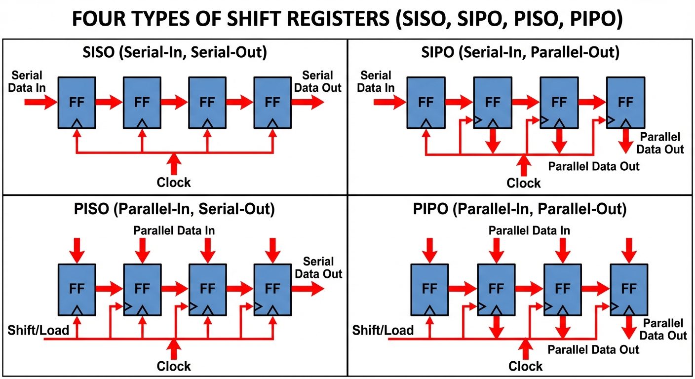
C. Parallel-In Serial-Out (PISO)
- Data Entry: Parallel (all bits loaded simultaneously via a load/shift control).
- Data Output: Serial.
- Operation:
- Requires combinational logic (AND/OR gates) at the inputs to switch between "Load Mode" (parallel input) and "Shift Mode" (serial movement).
- Data is loaded in 1 clock cycle; shifted out in cycles.
- Application: Parallel-to-Serial conversion (e.g., sending data to a USB port).
D. Parallel-In Parallel-Out (PIPO)
- Data Entry: Parallel.
- Data Output: Parallel.
- Operation:
- Output follows input immediately upon the active clock edge.
- No shifting of data occurs between flip-flops; they operate independently but share a clock.
- Application: Temporary storage (Buffer registers), delay matching.
2. Counters
A counter is a sequential circuit that proceeds through a predetermined sequence of states upon the application of input pulses.
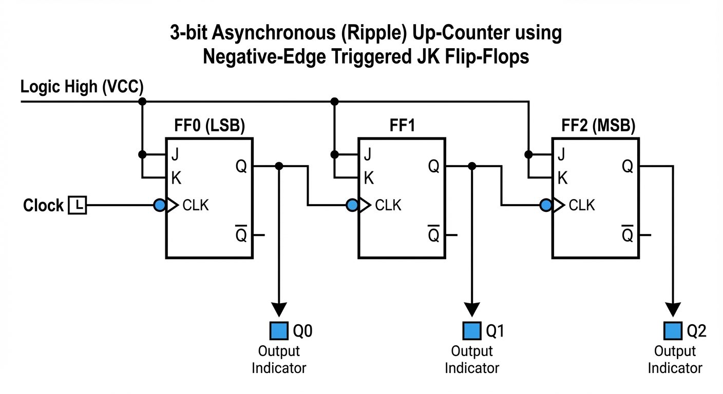
2.1 Asynchronous (Ripple) Counters
In asynchronous counters, the external clock signal is applied only to the first flip-flop (LSB). The output of the first FF acts as the clock for the second, the second for the third, and so on.
Operation Principles
- Flip-Flop Type: Usually T-FF or JK-FF wired to toggle (J=K=1).
- Ripple Effect: The state change "ripples" through the chain from LSB to MSB. This creates a propagation delay accumulation.
A. Asynchronous UP Counter
- The first FF (FF0) is clocked by the external clock.
- The output of FF0 drives the clock input of FF1.
- Triggering:
- If using Negative Edge Triggered FFs: Connect to the next Clock input.
- If using Positive Edge Triggered FFs: Connect to the next Clock input.
- Sequence: .
B. Asynchronous DOWN Counter
- Counts from maximum value down to 0.
- Triggering:
- If using Negative Edge Triggered FFs: Connect to the next Clock input.
- If using Positive Edge Triggered FFs: Connect to the next Clock input.
C. Mod-N Asynchronous Counter
A counter that resets after states (counting 0 to ) is a Modulo-N counter.
- Example: Mod-6 Counter (0 to 5):
- Requires 3 Flip-Flops ( states).
- Reset Condition: When count reaches 6 (binary 110).
- Logic: Use a NAND gate. Connect (4) and (2) to the NAND gate inputs. Connect the NAND output to the asynchronous CLR (Clear) inputs of all flip-flops.
- When and , CLR activates, forcing state 000 immediately.
2.2 Synchronous Counters
In synchronous counters, the clock pulse is applied to all flip-flops simultaneously. This eliminates the cumulative propagation delay found in ripple counters, allowing for higher frequency operation.
A. Synchronous UP Counter
- Logic: An FF should toggle only if all preceding bits are High (1).
- FF0 (LSB): Toggles on every clock (J=K=1).
- FF1: Toggles when .
- FF2: Toggles when AND .
- Hardware: Requires AND gates between stages to carry the logic.
B. Synchronous DOWN Counter
- Logic: An FF should toggle only if all preceding bits are Low (0).
- Hardware: Similar to the UP counter, but uses (Q-bar) outputs to drive the AND gates for the subsequent J/K inputs.
C. Mod-N Synchronous Counter
Designing a synchronous Mod-N counter requires a systematic design procedure:
- Determine number of FFs needed.
- Draw the State Diagram.
- Create the Excitation Table (Present State vs. Next State vs. J/K inputs).
- Solve K-Maps for each J and K input.
- Draw the logic circuit.
Comparison: Asynchronous vs. Synchronous
| Feature | Asynchronous (Ripple) | Synchronous |
|---|---|---|
| Clocking | Only LSB clocked; others driven by previous output | All FFs clocked simultaneously |
| Speed | Slow (Propagation delays add up) | Fast (Delay is constant: 1 FF + gates) |
| Design | Simple hardware | Complex hardware (requires logic gates) |
| Glitches | Prone to decoding spikes/glitches | Glitch-free outputs |
3. Special Counters (Shift Register Counters)
These are synchronous counters designed by feeding the output of a serial shift register back to its input.
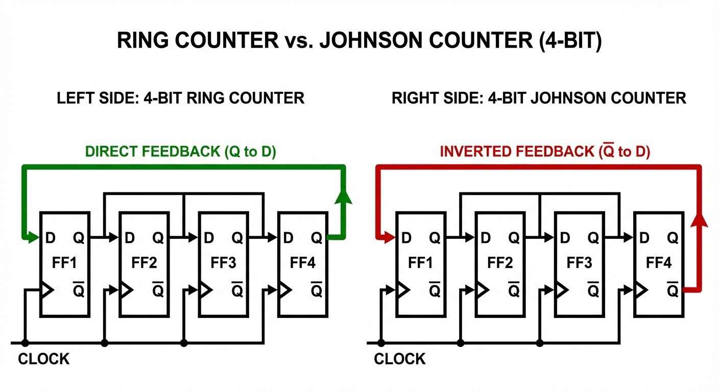
3.1 Ring Counter
A circular shift register.
- Structure: Output of the last FF () is connected to the D input of the first FF ().
- Initialization: Must be preset with a single "1" (e.g., 1000).
- Operation: The single "1" circulates through the register.
- Clock 1: 1000
- Clock 2: 0100
- Clock 3: 0010
- Clock 4: 0001
- Clock 5: 1000 (Repeats)
- Modulus: Mod-N (where N is the number of flip-flops).
- Disadvantage: Uses flip-flops to count states (inefficient compared to binary counters which count ).
3.2 Johnson Ring Counter (Twisted Ring Counter)
A modification of the ring counter that doubles the number of states.
- Structure: The inverted output of the last FF () is connected to the D input of the first FF ().
- Initialization: Usually reset to all zeros (0000).
- Operation (4-bit example):
- 0000 (Input receives which is 1)
- 1000
- 1100
- 1110
- 1111 (Input receives which is now 0)
- 0111
- 0011
- 0001
- 0000 (Repeats)
- Modulus: Mod-2N (counts states).
- Advantage: More efficient than a standard ring counter; used in multiphase clock generation.