Unit 3 - Notes
Unit 3: Input-Output Organization
1. Peripheral Devices
Peripheral devices are electromechanical or electromagnetic devices connected to the computer to allow communication with the outside world. They are not part of the central processing unit (CPU) or the primary memory but are essential for system functionality.
Classification of Peripherals
Peripheral devices are classified based on their function:
- Input Devices: Convert user data into binary information for the computer (e.g., Keyboard, Mouse, Digitizer, Scanner, Microphone).
- Output Devices: Convert binary data from the computer into a human-readable form (e.g., Printer, Monitor, Plotter, Speaker).
- Storage Devices (Mass Memory): Provide auxiliary storage for data (e.g., Magnetic Disks, Tapes, Optical Discs like CD/DVD).
The ASCII Standard
Most peripherals communicate using alphanumeric characters. The standard binary code for these characters is ASCII (American Standard Code for Information Interchange). It uses 7 bits to represent 128 characters (0–127), often extended to 8 bits to include an error-detection bit (parity) or extended characters.
2. Input-Output Interface
The Input-Output (I/O) Interface provides a method for transferring information between internal storage (RAM) and external I/O devices. Peripherals cannot be connected directly to the system bus due to several differences:
- Signal Mismatch: Peripherals are often electromechanical, while the CPU is electronic.
- Speed Mismatch: Peripherals are significantly slower than the CPU/Memory.
- Data Format: Peripherals may use different data formats (e.g., serial vs. parallel).
- Operating Modes: Peripherals operate autonomously and need synchronization mechanisms.
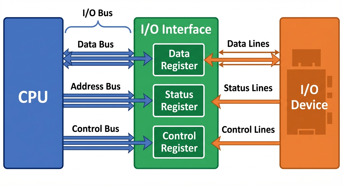
Functions of the Interface
- Data Buffering: holding data temporarily to smooth out speed differences.
- Control and Timing: coordinating the traffic between CPU and device.
- Status Reporting: indicating if the device is ready, busy, or has an error.
- Address Decoding: identifying which device the CPU is trying to access.
I/O Bus and Interface Modules
- Data Bus: Carries data in and out.
- Address Bus: Selects the specific I/O interface and register within it.
- Control Bus: Carries commands like I/O Read, I/O Write.
3. Modes of Data Transfer
Data transfer between the computer and an I/O device can be handled in three primary modes:
A. Programmed I/O
The CPU stays in a program loop until the I/O unit indicates that it is ready for data transfer. This is a time-consuming process as the CPU is busy checking the status (polling) and cannot execute other instructions.
- Mechanism: CPU reads a status register repeatedly -> If Ready -> Transfer Data.
- Drawback: "Busy-waiting" wastes CPU cycles.
B. Interrupt-Initiated I/O
To resolve the busy-waiting issue, the CPU issues an I/O command and proceeds to execute other tasks. When the interface is ready, it sends an interrupt signal to the CPU. The CPU stops its current task, saves its state, services the I/O transfer via an Interrupt Service Routine (ISR), and then resumes normal execution.
C. Direct Memory Access (DMA)
Used for large blocks of data. The interface transfers data directly to/from memory without CPU intervention. (Detailed in Section 5).
4. Priority Interrupt
When multiple devices issue interrupts simultaneously, the system must decide which to service first. This is handled via Priority Interrupt logic.
Polling (Software Method)
The CPU executes a routine that checks each device sequentially (via software) to see which one generated the interrupt.
- Pros: Simple hardware.
- Cons: Slow response time due to sequential checking.
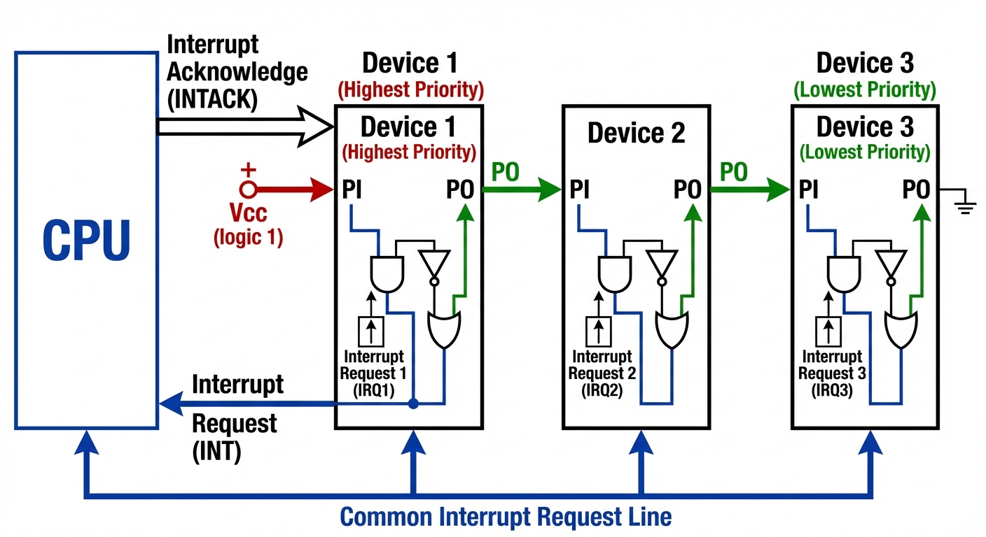
Daisy Chaining (Hardware Method)
A hardware mechanism where devices are connected in a serial chain.
- Mechanism: The CPU sends an INTACK (Interrupt Acknowledge) signal.
- Flow: The signal enters the highest priority device first. If that device initiated the interrupt, it blocks the signal and places its vector address on the data bus. If not, it passes the signal to the next device.
- Hierarchy: Priority is determined by the physical position in the chain.
Parallel Priority Interrupt
Uses a priority encoder hardware to determine the highest priority interrupt instantly, bypassing the serial delay of daisy chaining.
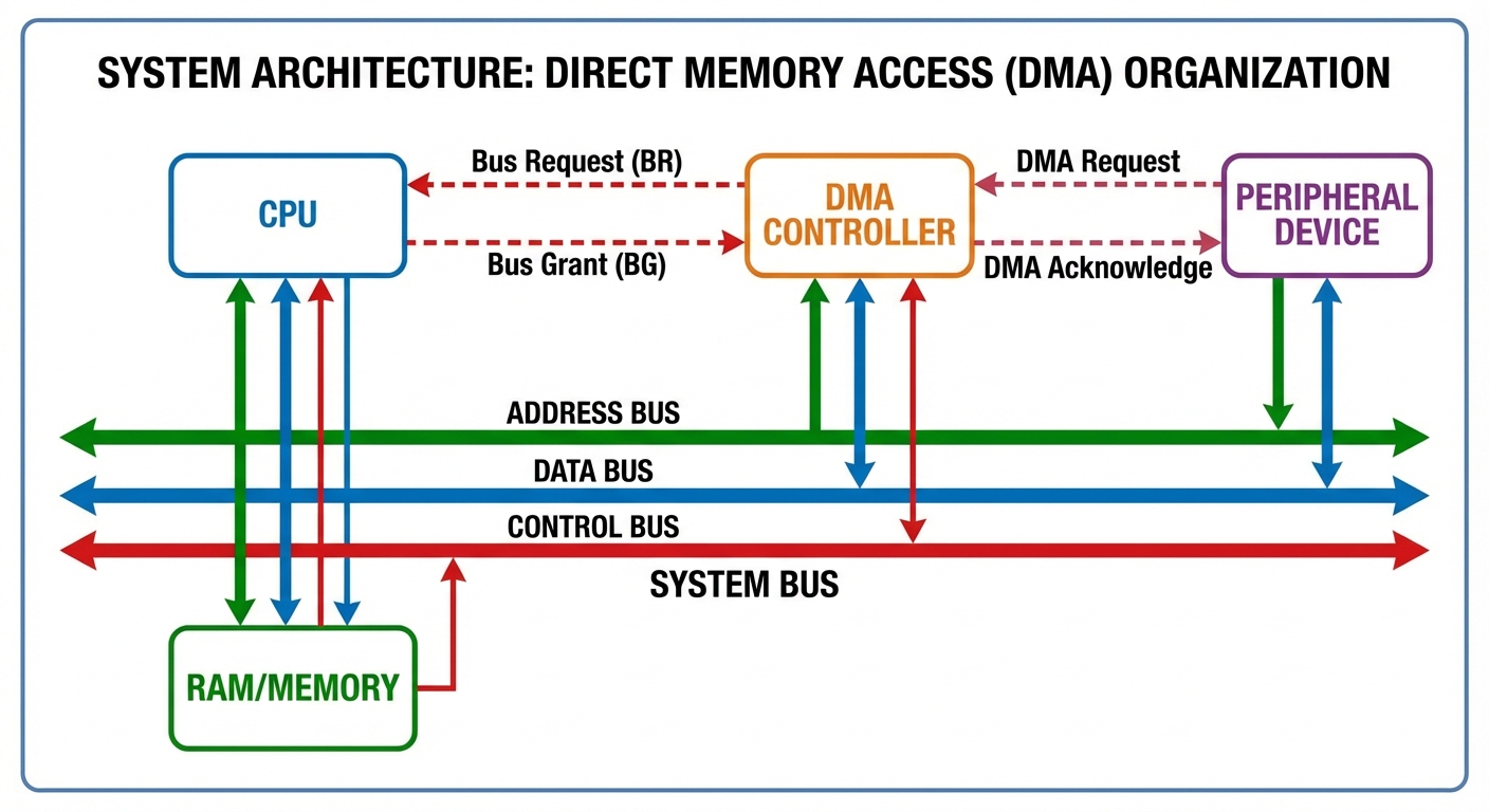
5. Direct Memory Access (DMA) Transfer
DMA is a hardware feature that allows I/O devices to access the main system memory independently of the CPU. This is crucial for high-speed devices like hard drives or network cards.
DMA Controller (DMAC)
The DMAC takes control of the system bus to transfer data.
- Bus Request (BR): DMAC asks CPU for control of the bus.
- Bus Grant (BG): CPU finishes current bus cycle, releases control, and signals DMAC.
- Transfer: DMAC manages the address and data lines to move data between Memory and I/O.
- Completion: DMAC releases the bus and interrupts the CPU to signal completion.
Modes of DMA Transfer
- Burst Mode: The DMA controller keeps control of the bus until the entire block of data is transferred. The CPU is idle for a longer duration.
- Cycle Stealing: The DMA controller takes control of the bus for one memory cycle to transfer one word/byte, then returns control to the CPU. It "steals" cycles from the CPU, slowing down instruction execution slightly but preventing long CPU blockage.
6. Input/Output Processor (IOP)
As systems became complex, DMA was not enough. The IOP is a dedicated processor with direct memory access capability that communicates with I/O devices.
Difference between DMA and IOP
- DMA: A hardware controller that transfers data. It needs CPU initialization for every block.
- IOP: A processor with its own instruction set (I/O instructions). It can execute a sequence of I/O operations (an I/O program) stored in memory without CPU intervention.
System Architecture with IOP
The CPU acts as the "Master" processor, handling processing tasks. The IOP acts as a "Slave" processor, handling all input/output details.
- Step 1: CPU sends a command to test the IOP path.
- Step 2: CPU sends the memory address of the I/O program to the IOP.
- Step 3: CPU continues with other work.
- Step 4: IOP executes the I/O program (fetching data, formatting, transferring).
- Step 5: IOP interrupts the CPU when finished.
7. UART (Universal Asynchronous Receiver-Transmitter)
UART is a hardware component responsible for serial communication. It translates data between parallel (used by the CPU/Bus) and serial (used by the communication line) forms.
Asynchronous Communication
Data is transferred one character at a time without a shared clock signal between sender and receiver. Synchronization is achieved using framing bits.
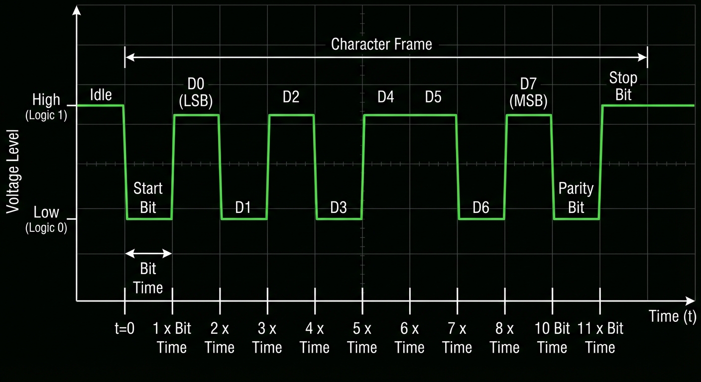
The Data Frame Format
A typical 10-bit or 11-bit character frame includes:
- Start Bit: Always 0 (Space). Signals the receiver that a character is starting. The line goes from High (Idle) to Low.
- Data Bits: Usually 5 to 8 bits representing the character (LSB first).
- Parity Bit: Optional bit for error detection (Odd or Even parity).
- Stop Bit(s): Always 1 (Mark). Signals the end of the character and returns the line to the Idle state.
UART Registers
- Transmit Hold Register: Holds data waiting to be sent.
- Shift Register: Converts parallel data to serial stream.
- Receiver Buffer Register: Holds received parallel data.
- Status Register: Flags for Parity Error, Framing Error, or Overrun Error.