Unit 2 - Notes
Unit 2: Central Processing Unit
1. General Register Organization
The CPU requires high-speed storage to perform operations efficiently without constantly accessing main memory. This storage is provided by a set of registers.
1.1 Bus System for Seven CPU Registers
In a typical organization, the CPU contains a set of general-purpose registers (e.g., R1 through R7) and an ALU. To transfer information among these registers and the ALU, a common bus system is used.
- Multiplexers (MUX): Used to select the source registers for the ALU. For example, if the ALU needs operands A and B, one set of MUXes selects the register for input A, and another set selects the register for input B.
- ALU (Arithmetic Logic Unit): Performs the operation selected by the operation control lines.
- Decoder: Used to select the destination register. The result from the ALU is directed to the input of all registers, but the load signal is enabled only for the specific register selected by the destination decoder.
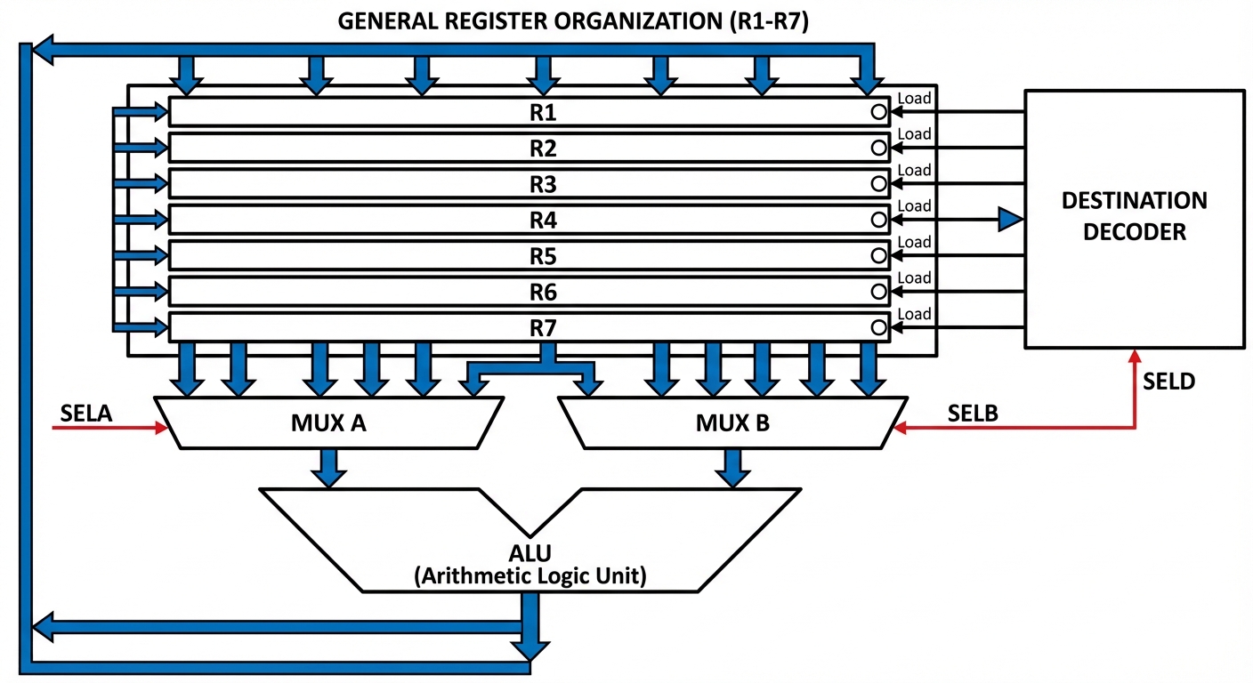
1.2 Control Word
The operation of the register unit is controlled by a control word, typically divided into fields:
- SELA (3 bits): Selects the first source register.
- SELB (3 bits): Selects the second source register.
- SELD (3 bits): Selects the destination register.
- OPR (4-5 bits): Selects the operation to be performed by the ALU (Add, Sub, XOR, etc.).
2. Stack Organization
A stack is a storage mechanism that operates on a Last In, First Out (LIFO) basis.
2.1 Register Stack
A stack can be implemented using a collection of registers and a Stack Pointer (SP).
- Stack Pointer (SP): A register that holds the address of the top item in the stack.
- PUSH Operation: Inserts an item.
SP <- SP + 1(Increment pointer)M[SP] <- DR(Write data)- Check for Overflow (if SP exceeds stack limit).
- POP Operation: Deletes an item.
DR <- M[SP](Read data)SP <- SP - 1(Decrement pointer)- Check for Underflow (if SP goes below 0).
2.2 Memory Stack
A stack can be implemented in random-access memory (RAM).
- Usually, the stack grows "downwards" (from high memory addresses to low addresses).
- PUSH:
SP <- SP - 1, thenM[SP] <- Data. - POP:
Data <- M[SP], thenSP <- SP + 1.
2.3 Reverse Polish Notation (RPN)
Arithmetic expressions are often converted to RPN (Postfix notation) to be evaluated efficiently by a stack.
- Infix:
(A + B) * C - Postfix:
A B + C * - Evaluation: Scan from left to right. Push operands. When an operator is found, pop the required number of operands, perform the operation, and push the result back.
3. Instruction Formats
The physical and logical layout of an instruction in memory. Fields usually include Opcode, Address/Operand, and Addressing Mode.
3.1 Types based on Operand Count
-
Three-Address Instructions:
- Format:
Opcode Dest, Src1, Src2 - Example:
ADD R1, A, B(R1 ← M[A] + M[B]) - Advantage: Short programs.
- Disadvantage: Long instruction bits.
- Format:
-
Two-Address Instructions:
- Format:
Opcode Dest, Src - Example:
ADD R1, A(R1 ← R1 + M[A]) - Most common in commercial computers.
- Format:
-
One-Address Instructions:
- Uses an implied Accumulator (AC) register.
- Format:
Opcode Operand - Example:
ADD B(AC ← AC + M[B])
-
Zero-Address Instructions:
- Uses a Stack.
- Format:
Opcode(Operands are implicitly the top two items on the stack). - Example:
ADD(Pop top two, add, push result).
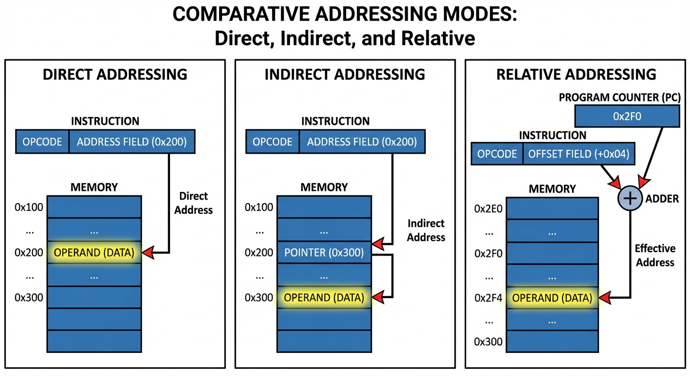
4. Addressing Modes
Addressing modes specify the rule for interpreting or modifying the address field of the instruction before the operand is actually executed. The address computed is called the Effective Address (EA).
| Mode | Mnemonic | Description | Effective Address (EA) |
|---|---|---|---|
| Implied | CLA | Operand is inherent in opcode (e.g., Complement Accumulator). | N/A |
| Immediate | LD #NBR | Operand is present in the instruction itself. | Operand = Address Field |
| Register | MOV R1 | Operand is in a CPU register. | EA = R (Register) |
| Register Indirect | MOV (R1) | Register contains the address of the operand. | EA = [R] |
| Direct | LD ADR | Address field contains the address of the operand. | EA = Address Field |
| Indirect | LD @ADR | Address field points to an address, which points to the operand. | EA = M[Address Field] |
| Relative | BEQ 20 | Address is relative to the Program Counter (PC). | EA = PC + Offset |
| Indexed | LD X(R1) | Uses an Index Register (XR) added to base. | EA = Address Field + XR |
| Base Register | Uses a Base Register added to displacement. | EA = Base Reg + Displacement |
5. Data Transfer Schemes
Efficient communication between the central computer (CPU + Memory) and the peripheral devices (I/O).
5.1 Programmed I/O
- The CPU stays in a program loop until the I/O unit indicates that it is ready for data transfer.
- Drawback: CPU time is wasted polling the status of the device ("busy waiting").
5.2 Interrupt-Initiated I/O
- The CPU proceeds with program execution.
- When the peripheral is ready, it sends an Interrupt Request signal.
- The CPU stops current execution, saves its state, services the I/O transfer, and then returns to the original program.
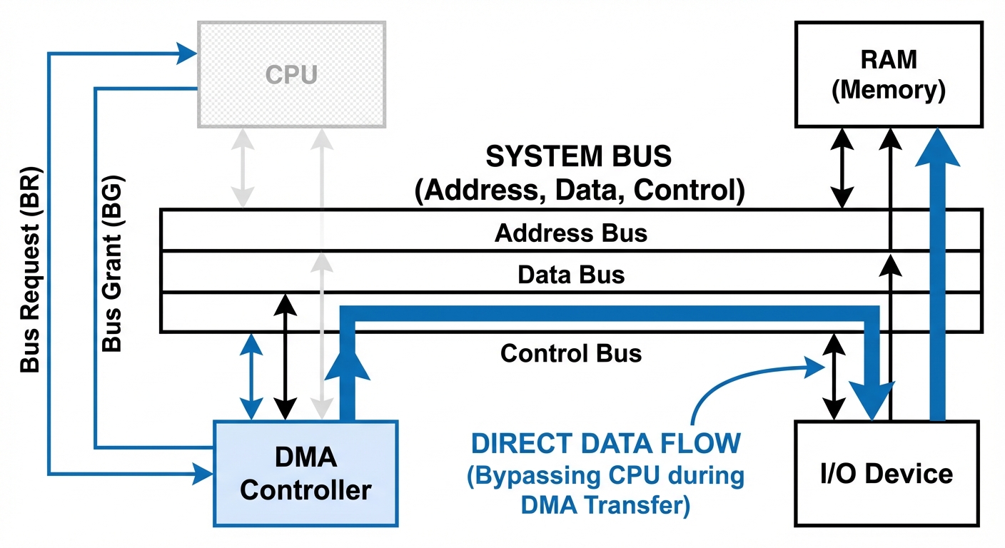
5.3 Direct Memory Access (DMA)
- Used for large blocks of data transfer (e.g., Disk to RAM).
- DMA Controller (DMAC): Takes control of the system bus from the CPU.
- Bus Request (BR): DMAC asks CPU for the bus.
- Bus Grant (BG): CPU grants the bus.
- Burst Transfer: Data is transferred directly between I/O and Memory without passing through the CPU.
6. Program Control and Interrupts
6.1 Program Control Instructions
These instructions change the flow of the program (modify the Program Counter).
- Branch (JMP): Unconditional jump to an address.
- Conditional Branch: Jump only if a specific flag (Z, S, C, V) is set (e.g.,
BZ- Branch if Zero). - Subroutine Call (CALL): Jumps to a sub-program and saves the Return Address (usually on the Stack).
- Return (RET): Restores the Return Address to the PC.
6.2 Processor Status Word (PSW)
The PSW is a composite register that contains status information and control bits. It typically includes:
- Status Flags (Condition Codes):
- C (Carry): Set if an arithmetic carry occurs (unsigned overflow).
- S (Sign): Set if the MSB of the result is 1 (negative).
- Z (Zero): Set if the result is 0.
- V (Overflow): Set if signed overflow occurs (XOR of carry-in and carry-out of MSB).
- Control Bits: Interrupt Enable, Supervisor/User Mode bit.
6.3 Interrupt Cycle
An interrupt is a mechanism to break the normal sequence of operations.
- Types:
- External: From I/O devices, timing devices.
- Internal (Traps): Error conditions (Divide by zero, stack overflow).
- Software: Initiated by executing an instruction (System Calls).
- Handling Process:
- CPU finishes current instruction.
- Checks for pending interrupt.
- Pushes PC (Return Address) and PSW to the stack.
- Loads the Vector Address of the Interrupt Service Routine (ISR) into the PC.
- Executes ISR.
- Restores PC and PSW from stack to resume.
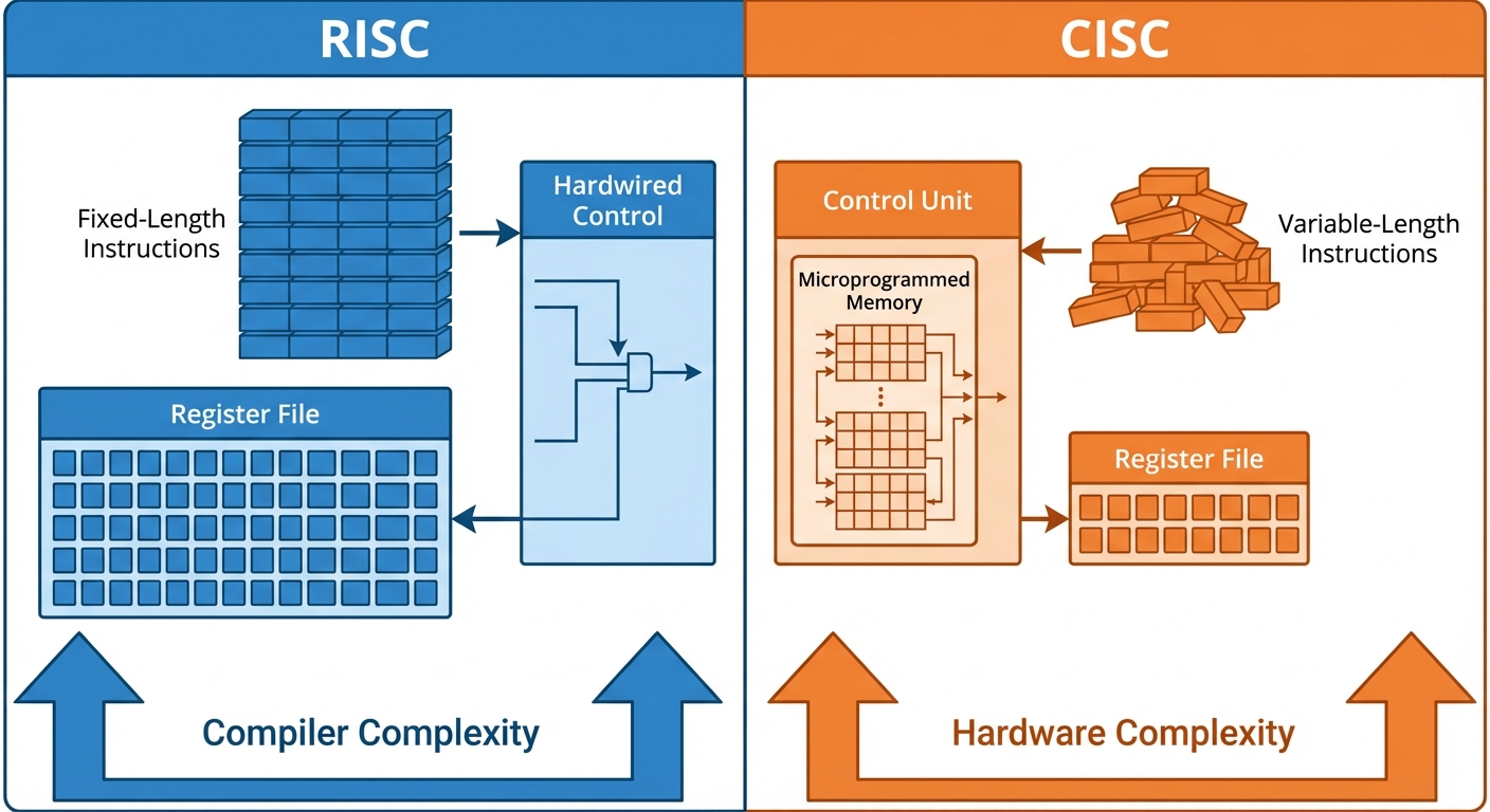
7. RISC vs. CISC
Modern CPU architectures are generally classified into two categories based on instruction set complexity.
7.1 Complex Instruction Set Computer (CISC)
- Philosophy: Hardware should do more. One instruction can execute a complex series of low-level operations.
- Examples: Intel x86.
- Characteristics:
- Large number of instructions (100-200+).
- Variable-length instruction formats (1 byte to 15 bytes).
- Many addressing modes.
- Microprogrammed Control Unit: Instructions are decoded into microcode stored in ROM.
- Emphasis on code density (smaller program size in memory).
7.2 Reduced Instruction Set Computer (RISC)
- Philosophy: Keep instructions simple so they can execute in one clock cycle. Software (compiler) handles complexity.
- Examples: ARM, MIPS.
- Characteristics:
- Small set of simple instructions.
- Fixed-length instruction formats (usually 32-bit).
- Few addressing modes.
- Hardwired Control Unit: Faster execution.
- Large Register File: Reduces need for memory access.
- Highly optimized for Pipelining.
- Load/Store Architecture: Only Load and Store instructions access memory; arithmetic is done in registers.
7.3 Comparison Summary
| Feature | RISC | CISC |
|---|---|---|
| Instruction Complexity | Simple, single-cycle | Complex, multi-cycle |
| Instruction Length | Fixed | Variable |
| Registers | Many | Few |
| Memory Access | Load/Store only | Any instruction can access memory |
| Control Unit | Hardwired (Faster) | Microprogrammed (Flexible) |
| Pipelining | Easy / Highly effective | Difficult due to variable lengths |