Unit 1 - Notes
Unit 1: Computer Organization
This unit covers the fundamental structural layout of a computer system, focusing on the Basic Computer model (often associated with M. Morris Mano's architecture). It details how instructions are defined, stored, fetched, and executed through the coordination of registers, buses, and control logic.
1. Instruction Codes
An instruction code is a group of bits that tells the computer to perform a specific operation. The organization of the stored program computer relies on code formats.
Stored Program Organization
A computer has a memory unit to store instructions and data. The Accumulator (AC) register is generally used for processing data.
Instruction Format
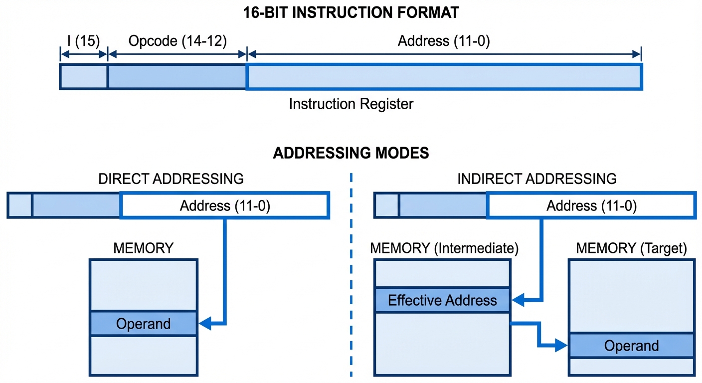
In a standard 16-bit Basic Computer, the instruction format is divided as follows:
- Bits 0-11 (Address): Specifies the operand address in memory (12 bits).
- Bits 12-14 (Opcode): Specifies the operation to be performed (3 bits). e.g., ADD, AND, LOAD.
- Bit 15 (Addressing Mode - I): Distinguishes between direct and indirect addressing.
| I (Bit 15) | Opcode (Bits 14-12) | Address (Bits 11-0) |
|---|---|---|
| 0 = Direct | Operation Code | Operand Address |
| 1 = Indirect | Operation Code | Pointer to Operand Address |
Addressing Modes:
- Direct Addressing (I=0): The address part of the instruction contains the actual location of the operand.
- Indirect Addressing (I=1): The address part contains a memory location, which in turn holds the actual address of the operand.
2. Computer Registers
Registers are high-speed storage units within the CPU used to hold data, addresses, and instructions during processing.
List of Basic Computer Registers
| Register Symbol | Bits | Register Name | Function |
|---|---|---|---|
| DR | 16 | Data Register | Holds memory operand/data. |
| AR | 12 | Address Register | Holds address for memory. |
| AC | 16 | Accumulator | Processor register (general purpose). |
| IR | 16 | Instruction Register | Holds instruction code. |
| PC | 12 | Program Counter | Holds address of the next instruction. |
| TR | 16 | Temporary Register | Holds temporary data. |
| INPR | 8 | Input Register | Holds input character. |
| OUTR | 8 | Output Register | Holds output character. |
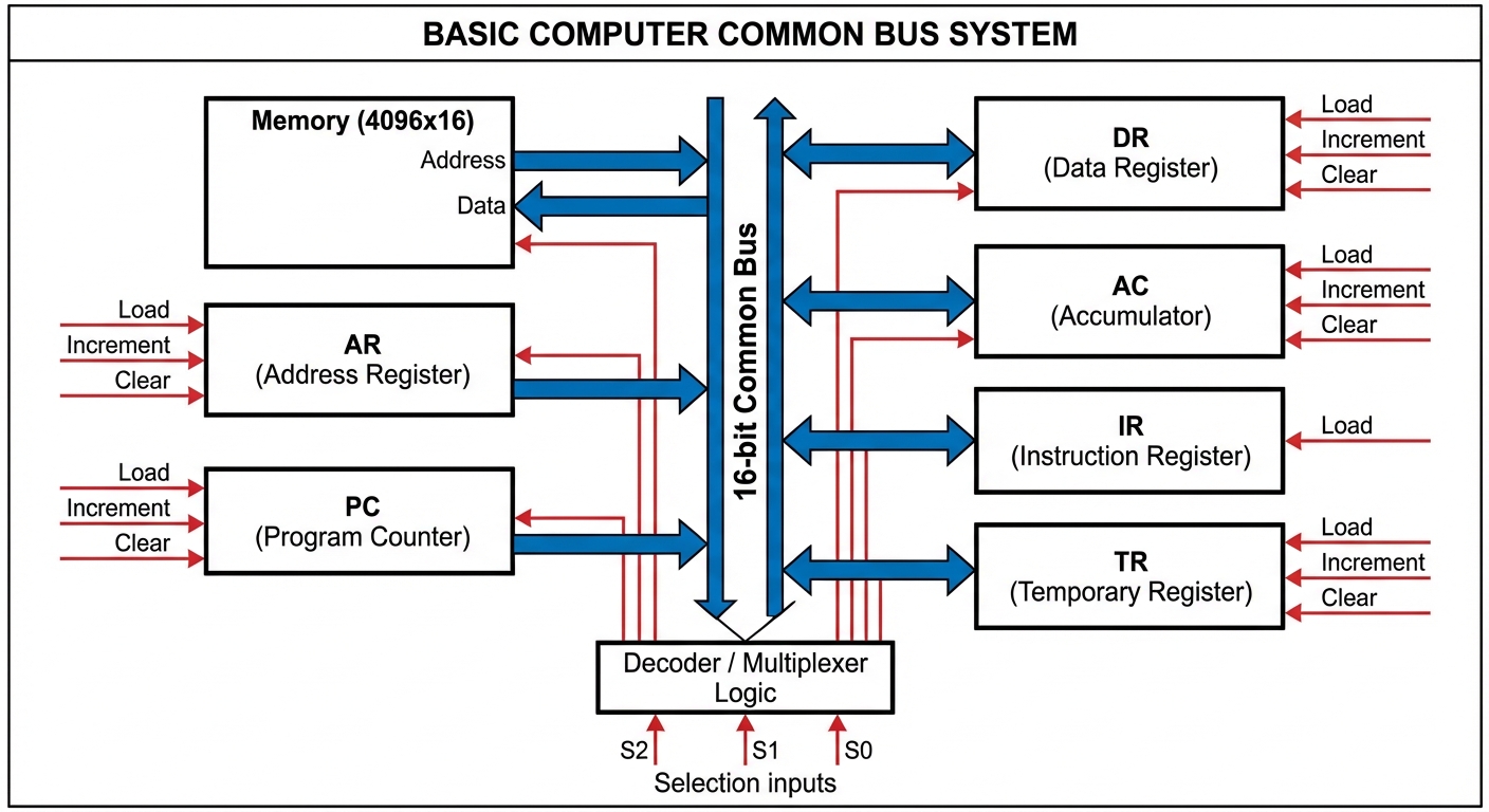
3. Common Bus System
To avoid complex wiring between every register and memory, a Common Bus is used. It provides a shared path for information transfer.
Architecture
- Multiplexers (MUX): The bus is typically constructed using multiplexers. For a system with 8 registers, a set of 8x1 multiplexers is used.
- Selection Lines (S2, S1, S0): These control inputs determine which register places its data onto the bus.
- Load Control: Destination registers have a "Load" (LD) control input. When LD is high, the data on the bus is transferred into that register.
Logic
If (Binary 4), the specific register associated with index 4 (e.g., AC) is selected, and its content is placed on the bus.
4. Computer Instructions
The Basic Computer instruction set is classified into three types based on the Opcode (bits 12-14) and the Mode bit (15).
-
Memory Reference Instructions (MRI):
- Opcode: 000 through 110.
- Operate on data stored in memory.
- Example:
AND,ADD,LDA(Load to AC),STA(Store AC).
-
Register Reference Instructions (RRI):
- Opcode: 111, with I-bit (Bit 15) = 0.
- Operate on the Accumulator or Status bits. No memory access.
- Example:
CLA(Clear AC),CMA(Complement AC),HLT(Halt). - Recognized by Hex code .
-
Input-Output Instructions (IOI):
- Opcode: 111, with I-bit (Bit 15) = 1.
- Control Input/Output and Interrupts.
- Example:
INP(Input char),OUT(Output char). - Recognized by Hex code .
5. Timing and Control
All computer operations are synchronized by a master clock generator.
- Clock Pulses: Determine the timing intervals.
- Sequence Counter (SC): A 4-bit counter that produces time signals .
- Hardwired Control:
- Logic gates combine Instruction Decoder outputs ( to ) and Timing Signals ( to ) to generate control signals.
- Example: Control function means "Perform operation P when opcode is decoded as and time is ."
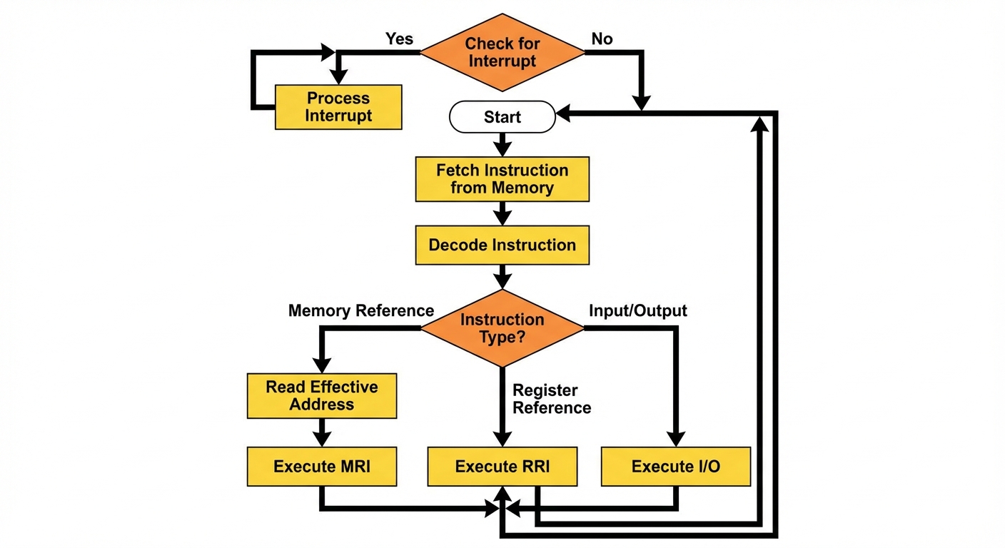
6. Instruction Cycle
The instruction cycle is the process the CPU follows to process a single instruction. It repeats indefinitely until the computer is turned off or halted.
The Four Phases
- Fetch: Read the instruction from memory.
- Decode: Decode the instruction to determine the operation.
- Read Effective Address: If the instruction is indirect, read the memory again to get the actual operand address.
- Execute: Perform the operation.
Fetch and Decode (Register Transfer Language)
The Fetch phase is common to all instructions:
- : (Move Program Counter to Address Register)
- : (Read Memory to Instruction Register; Increment PC)
- : (Decode Opcode; Move Address part to AR)
7. Memory Reference Instructions (MRI) Details
These instructions require access to memory (RAM) to fetch operands.
- AND (): Logic AND operand with AC.
- ADD (): Add operand to AC (Carry is stored in E flip-flop).
- LDA (): Load data from Memory to AC.
- STA (): Store data from AC to Memory.
- BUN (): Branch Unconditionally (Jump). .
- BSA (): Branch and Save Return Address (Subroutine Call).
- ISZ (): Increment Memory and Skip next instruction if Zero (Used for loops).
8. Input-Output and Interrupt
I/O Configuration
- Input Register (INPR): Receives serial data from keyboard.
- Output Register (OUTR): Holds data for printer/monitor.
- Flags:
- FGI (Input Flag): Set when INPR is ready.
- FGO (Output Flag): Set when OUTR is free.
Interrupt System
To prevent the CPU from idling while waiting for slow I/O (Programmed I/O), an Interrupt system is used.
- IEN (Interrupt Enable Flip-flop): Can be set/reset by programmer.
- Interrupt Cycle:
- At the end of an execution cycle (Time ), the CPU checks if an interrupt is pending ( AND ( OR )).
- If yes, the CPU saves the return address () into memory location 0.
- Branches to memory location 1 to execute the service routine.
- Clears IEN to 0.
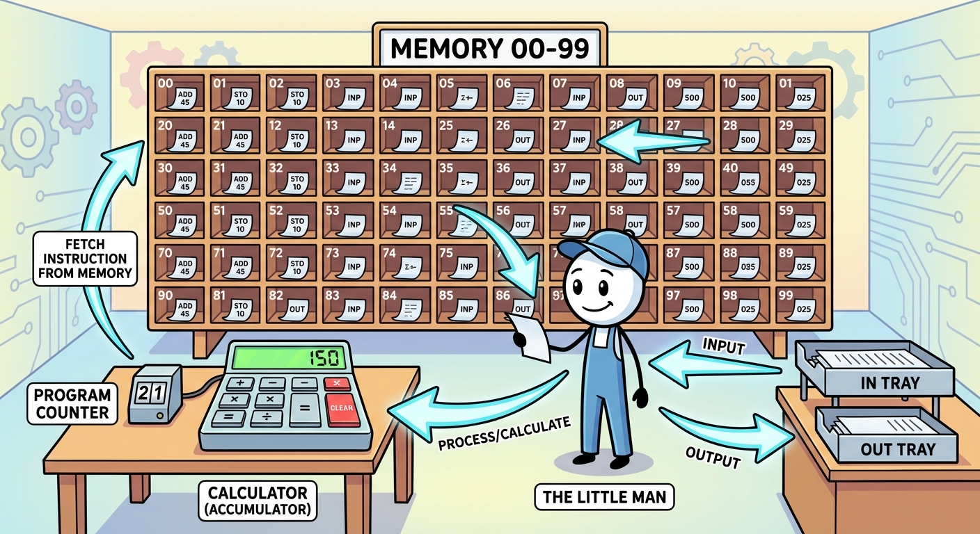
9. Little Man Computer (LMC)
The LMC is an instructional model of a computer, created by Dr. Stuart Madnick, that simulates a von Neumann architecture. It simplifies complex hardware into a metaphor.
The Metaphor
- The Little Man: Represents the Control Unit (CU) and Arithmetic Logic Unit (ALU).
- Mailboxes: Represent Memory (RAM). Numbered 00-99.
- Calculator: Represents the Accumulator (AC).
- In/Out Baskets: Represent Input and Output devices.
- Instruction Counter: Represents the Program Counter (PC).
LMC Instruction Set (Mnemonics & Codes)
Each instruction is a 3-digit number (1 digit opcode, 2 digits address).
| Mnemonic | Code | Description |
|---|---|---|
| ADD | 1xx | Add value in mailbox xx to Calculator. |
| SUB | 2xx | Subtract value in mailbox xx from Calculator. |
| STA | 3xx | Store value from Calculator to mailbox xx. |
| LDA | 5xx | Load value from mailbox xx to Calculator. |
| BRA | 6xx | Branch Always (Jump) to mailbox xx. |
| BRZ | 7xx | Branch if Zero (Calculator == 0) to xx. |
| BRP | 8xx | Branch if Positive (Calculator >= 0) to xx. |
| INP | 901 | Input value to Calculator. |
| OUT | 902 | Output value from Calculator. |
| HLT | 000 | Halt / Coffee Break. |