Unit 2 - Notes
Unit 2: Software Design Principles & System Architecture
1. Basic Principles of Software Design
Software design is the process of transforming user requirements (from the SRS) into a suitable form that helps the programmer in coding and implementation. It serves as a blueprint for the system.
Core Design Principles
- Abstraction: Hiding low-level details and focusing on essential characteristics.
- Functional Abstraction: Specifying what a module does without stating how.
- Data Abstraction: Defining data types and operations without revealing implementation details.
- Refinement: The stepwise process of elaboration. It moves from a high-level abstraction to low-level implementation details (Top-Down approach).
- Information Hiding: Design decisions that are likely to change (e.g., specific algorithms or data structures) should be hidden within a module. This creates an interface that isolates the client from the implementation.
- Simplicity: The design should be as simple as possible to minimize complexity and potential errors.
Modularity
Modularity is the practice of dividing a software system into distinct, independent, and named components called modules. A module is a logically separable part of a program.
- Divide and Conquer: Breaking a complex problem into smaller, manageable sub-problems.
- Benefits:
- Reusability: Modules can be used in other programs.
- Maintainability: Errors are localized to specific modules.
- Parallel Development: Different teams can work on different modules simultaneously.
2. Cohesion and Coupling (Measuring Module Independence)
Module independence is the single most important criterion for good design. It is measured using two quantitative metrics: Cohesion and Coupling.
The Golden Rule of Design: Aim for High Cohesion and Low Coupling.
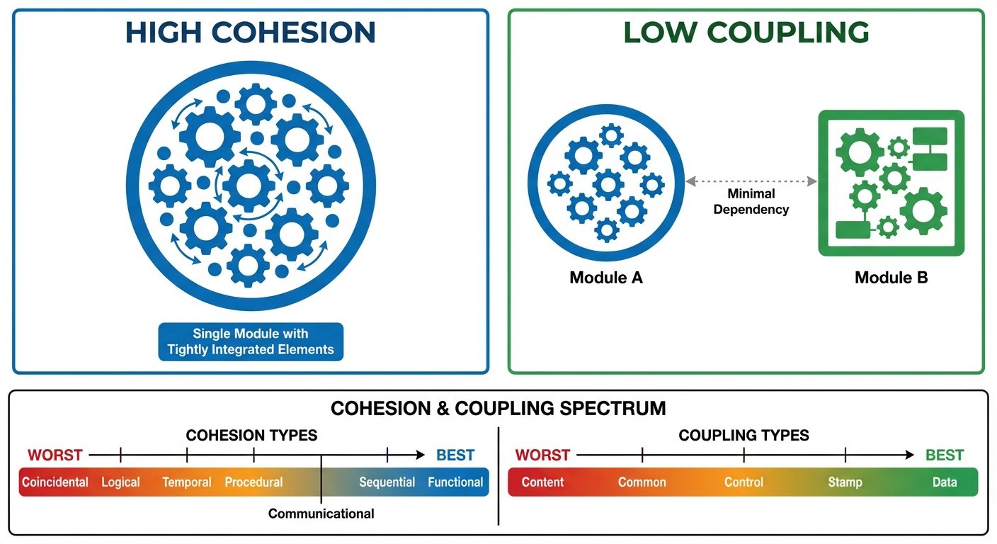
Cohesion (Internal Strength)
Cohesion measures the strength of the relationship between the elements within a single module. It indicates how functionally related the operations within a module are.
Types of Cohesion (Ordered from Best to Worst):
- Functional Cohesion (Best): All elements contribute to the execution of a single, specific task (e.g.,
CalculateTax). - Sequential Cohesion: The output of one element serves as the input to the next element within the module.
- Communicational Cohesion: Elements operate on the same input data or produce the same output data.
- Procedural Cohesion: Elements are grouped because they are executed in a specific sequence/order.
- Temporal Cohesion: Elements are grouped because they happen at the same time (e.g.,
SystemInitializationorErrorHandling). - Logical Cohesion: Elements are logically related (e.g., a module performing all input operations: mouse, keyboard, network), but the specific action depends on a control flag.
- Coincidental Cohesion (Worst): Elements are grouped arbitrarily with no meaningful relationship (often resulting from "spaghetti code").
Coupling (External Dependency)
Coupling measures the degree of interdependence between different modules. Lower coupling allows modules to be modified without affecting others.
Types of Coupling (Ordered from Best to Worst):
- Data Coupling (Best): Modules communicate by passing only necessary data items (parameters). The modules are independent of each other's structure.
- Stamp Coupling: Modules share a composite data structure (like a
structorrecord), even if they only use parts of it. - Control Coupling: One module passes a control flag (like a boolean) to another, intending to control its logic. This requires the sender to know the internal logic of the receiver.
- External Coupling: Modules rely on external hardware, communication protocols, or external formats.
- Common Coupling: Multiple modules share the same global data area. A change in the global data definition affects all modules.
- Content Coupling (Worst): One module directly accesses or modifies the internal data or code of another module (e.g.,
GOTOinto the middle of another function).
Design Trade-offs
Achieving the perfect design often involves compromise.
- Performance vs. Modularity: Excessive modularity (too many function calls) can introduce overhead, slightly reducing speed.
- Security vs. Usability: Complex encryption increases security but may slow down the system or complicate the user experience.
- Time vs. Cost: A highly cohesive, low-coupled architecture takes longer to design but reduces maintenance costs long-term.
3. Function-Oriented Design: Data Flow Diagrams (DFD)
Function-oriented design views the system as a set of interacting functions. The primary tool for this is the Data Flow Diagram (DFD).
What is a DFD?
A DFD represents the flow of data through a system. It shows what the system does, not how it does it. It is a graphical representation of data movement, transformations, and storage.
Symbols and Notations (Gane & Sarson vs. Yourdon)
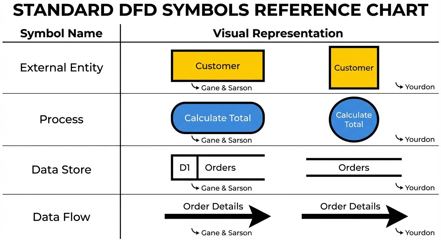
- External Entity (Source/Sink): Something outside the system that sends data into it or receives data from it (e.g., User, Admin, External Sensor). Represented by a Square or Rectangle.
- Process: A function or transformation that changes data input into output. Represented by a Circle or Rounded Rectangle.
- Data Store: A repository where data is stored for later use (e.g., Database, File, Filing Cabinet). Represented by Parallel Lines or an Open-ended Rectangle.
- Data Flow: The route data takes between entities, processes, and stores. Represented by an Arrow.
DFD Leveling and Hierarchy
DFDs are created in layers to handle complexity (Top-Down approach).
- Context Diagram (Level 0 DFD):
- The highest level.
- Represents the entire system as a single process bubble.
- Shows interaction with external entities only.
- No data stores are usually shown at this level unless they are external systems.
- Level 1 DFD:
- Decomposes the Context Diagram's single process into major sub-processes (typically 3-7 bubbles).
- Reveals internal data stores.
- Level 2 DFD:
- Further decomposition of specific processes from Level 1 into more detailed sub-processes.
Rules for Constructing DFDs
- Process Input/Output: Every process must have at least one input and one output.
- Data Conservation: Data cannot disappear into a process or be spontaneously generated (Black Hole/Miracle errors).
- Entity Interactions: Entities cannot communicate directly with each other; they must go through a process.
- Store Interactions: Data stores cannot communicate directly with other stores or entities; data must move through a process.
- Unique Names: Every process should have a unique verb-phrase name (e.g., "Calculate Bill," "Verify User").
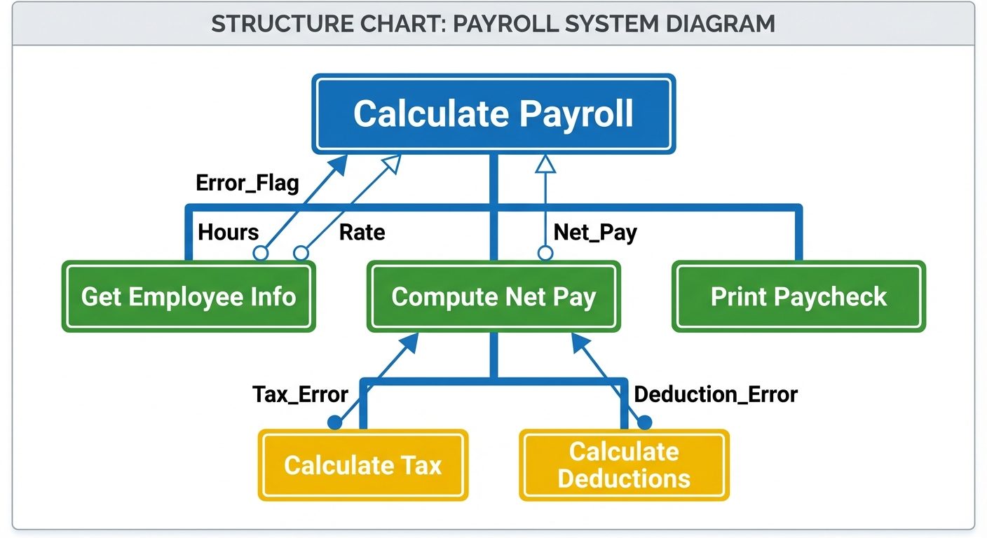
4. Structure Charts
While DFDs model data flow, Structure Charts model the hierarchy of modules and the control flow between them. It is the primary output of Architectural Design.
Components and Notation
- Module: Represented by a Rectangle. It denotes a named task or function (e.g.,
Main,Get_Input). - Connection: An Arrow connecting modules implies a call relationship (Module A calls Module B).
- Data Couple: An arrow with an Empty Circle at the tail. Represents passing data (e.g.,
Student_ID). - Control Couple (Flag): An arrow with a Filled Circle at the tail. Represents passing control information (e.g.,
End_of_File,Error_Found). - Loops/Conditionals: Curved arrows crossing module connections indicate iteration; diamond shapes indicate conditional calls.
Transform and Transaction Analysis
These are strategies to convert a DFD into a Structure Chart.
1. Transform Analysis
- Used when the dominant work of the system is transforming input data into output data.
- Steps:
- Identify the main "Central Transform" in the DFD (where the logic happens).
- Create a root module.
- Create three branches: Input Controller (Afferent), Transform Controller (Central), and Output Controller (Efferent).
2. Transaction Analysis
- Used when a single input splits into many different processing paths based on the input type (e.g., a menu selection: 1. Add, 2. Delete, 3. Update).
- Structure: A "Dispatcher" module evaluates the transaction type and calls the specific worker module responsible for that transaction.
5. Design Documentation & Review Techniques
Design Documentation
After the design phase, the Software Design Document (SDD) is produced.
- Purpose: To describe the architecture, data structures, algorithms, and interfaces.
- Key Sections:
- Data Design: ER Diagrams, Database Schema.
- Architectural Design: Structure Charts, System Block Diagrams.
- Interface Design: UI mockups, API specifications.
- Procedural Design: Pseudocode or Flowcharts for complex algorithms.
Design Review Techniques
Reviews are critical for Quality Assurance (QA) to find defects before coding begins.
-
Walkthroughs (Informal):
- The designer guides a team (peers) through the design document.
- Goal: Knowledge sharing and sanity checking.
- Not graded; usually no formal log of errors.
-
Inspections (Formal):
- A rigorous, structured process.
- Roles: Moderator, Author, Reader, Recorder.
- Checklists: Reviewers use predefined checklists to find specific errors (e.g., "Are all variables initialized?", "Is there a module with high coupling?").
- Outcome: A formal report of defects to be fixed before approval.
-
Technical Reviews:
- Focuses on technical accuracy and adherence to standards.
- Ensures the design is feasible with the available technology.