Unit 3 - Notes
Unit 3: Object-Oriented Software Development and Modeling Techniques
1. The Unified Process (UP)
The Unified Process (UP) is an iterative and incremental software development process framework. It is use-case driven, architecture-centric, and iterative/incremental.
Key Characteristics
- Iterative and Incremental: The project is divided into mini-projects (iterations). Each iteration results in an increment—a release of the system that contains added or improved functionality.
- Use-Case Driven: Development is driven by user requirements expressed as use cases.
- Architecture-Centric: The system architecture is established early and evolves to ensure stability and scalability.
Phases of the Unified Process
The UP is structured into four distinct phases. Each phase concludes with a major milestone.
-
Inception Phase:
- Goal: Establish the business case and scope.
- Activities: Identify primary external actors, define critical use cases, estimate costs/schedule, and assess risks.
- Milestone: Lifecycle Objectives (LCO).
-
Elaboration Phase:
- Goal: Analyze the problem domain and establish a sound architectural foundation.
- Activities: Address highest-risk items, detail the majority of use cases, and create an executable architecture prototype.
- Milestone: Lifecycle Architecture (LCA).
-
Construction Phase:
- Goal: Develop the remaining components and application features.
- Activities: Coding, integration, and testing of the complete system. This phase is usually the longest and requires the most resources.
- Milestone: Initial Operational Capability (IOC).
-
Transition Phase:
- Goal: Transition the software to the user community.
- Activities: Beta testing, user training, data conversion, and deployment.
- Milestone: Product Release.
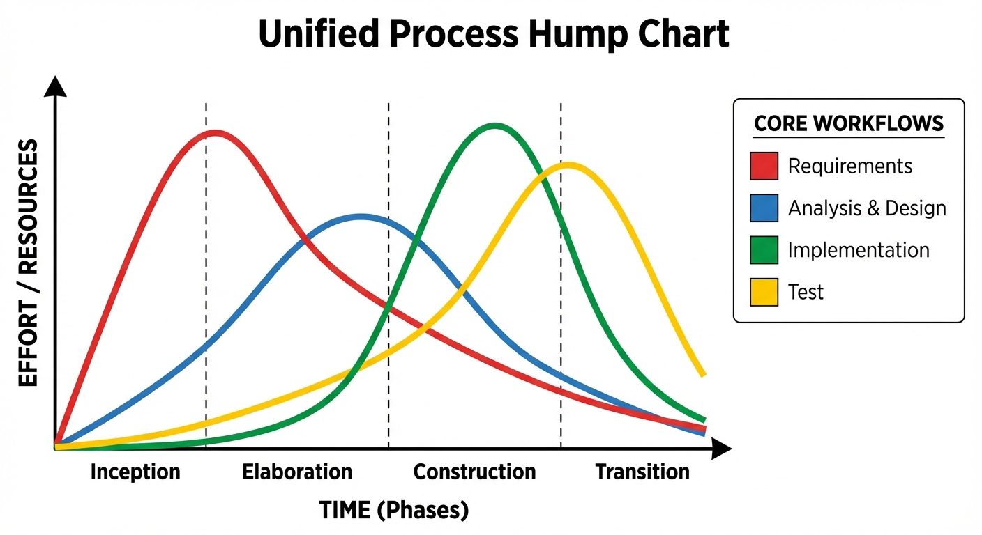
Core Workflows (Disciplines)
Workflows run across the phases, but with varying levels of effort depending on the current phase.
- Requirements: Capturing what the system should do.
- Analysis: Refining requirements and structuring them.
- Design: Shaping the system architecture and components.
- Implementation: Coding and building.
- Test: Verifying that the implementation matches requirements.
2. UML Modeling
The Unified Modeling Language (UML) is a standard visual modeling language intended to be used for the modeling of business and software systems.
A. Use Case Diagrams
Used to depict the functional requirements of a system. It captures the dynamic behavior of a system from the user's perspective.
- Key Elements:
- Actor: Represents a role played by a user or external system (Stick figure).
- Use Case: Represents a specific functionality or goal (Oval).
- System Boundary: A rectangle defining the scope of the system.
- Relationships:
- Association: Solid line connecting Actor and Use Case.
- Include (
<<include>>): The base use case explicitly incorporates the behavior of another use case (Mandatory). - Extend (
<<extend>>): The base use case implicitly incorporates the behavior of another use case under certain conditions (Optional). - Generalization: Parent-child relationship between actors or use cases.
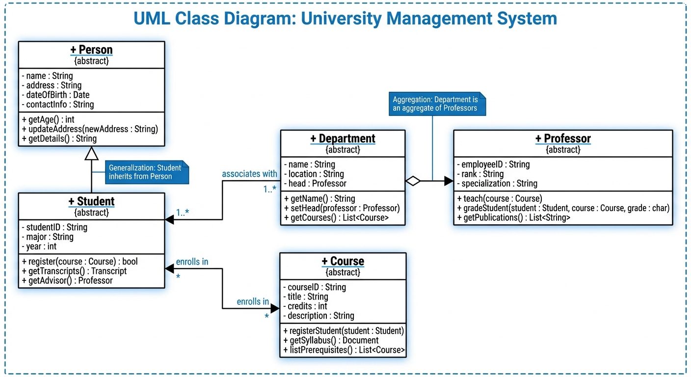
B. Class Diagrams
The central modeling technique for object-oriented design. It depicts the static structure of the system.
- Key Elements:
- Class: Represented by a rectangle divided into three compartments:
- Class Name
- Attributes (Variables)
- Methods (Operations)
- Class: Represented by a rectangle divided into three compartments:
- Relationships:
- Association: A structural link between classes (Solid line).
- Aggregation: "Has-a" relationship; weak ownership (Open diamond).
- Composition: "Part-of" relationship; strong ownership/lifecycle dependency (Filled diamond).
- Generalization (Inheritance): "Is-a" relationship (Hollow triangle arrow).
- Multiplicity: Indicates how many instances interact (e.g.,
1,0..1,1..*).
C. Sequence Diagrams
An interaction diagram that shows how objects operate with one another and in what order. It visualizes the dynamic behavior over time.
- Key Elements:
- Lifeline: Dashed vertical line representing the object's existence over time.
- Activation Bar: Thin rectangle on the lifeline indicating when an object is active/processing.
- Messages:
- Synchronous: Solid arrow with filled head (Request requiring response).
- Asynchronous: Solid arrow with open head (No wait for response).
- Return: Dashed arrow pointing back.
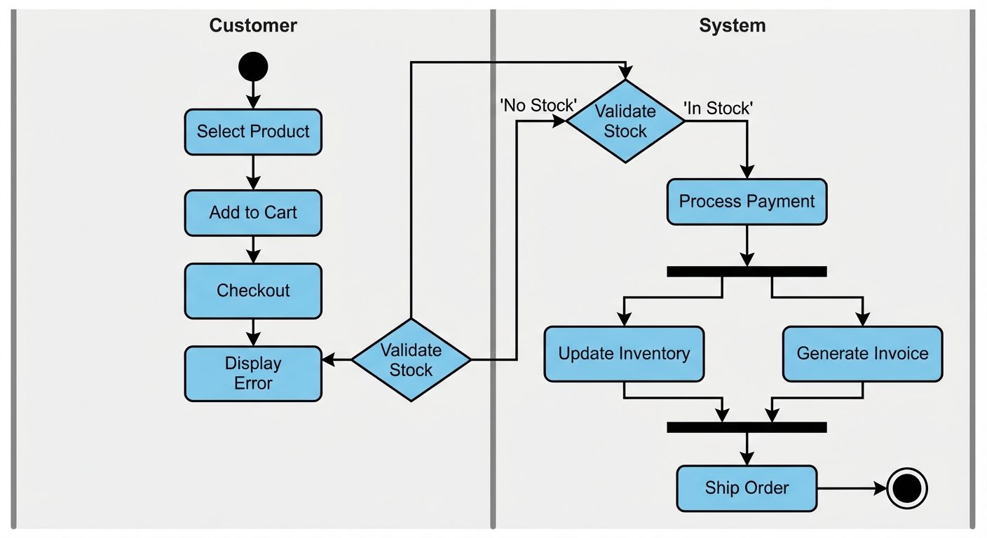
D. Activity Diagrams
A behavioral diagram that depicts the flow of control or data. It is similar to a flowchart but supports concurrency.
- Key Elements:
- Start Node: Solid black circle.
- Activity/Action State: Rounded rectangle representing a task.
- Decision Node: Diamond shape (Branching).
- Fork/Join: Thick black bars used to represent parallel processing (Concurrency).
- Swimlanes: Vertical or horizontal zones to group activities by responsibility (e.g., User vs. System).
3. Object Modeling Process & Validation
Object Modeling Process
This involves identifying the objects in the system and their relationships.
- Identification: Extract nouns from the requirements to find potential objects/classes.
- Refinement: Filter out irrelevant, vague, or redundant candidates.
- Attribute Definition: Identify data properties (fields) for each object.
- Association: Define how objects relate to one another.
- Behavior Definition: Assign methods/operations to classes.
Model Validation
Ensuring the design models are correct before coding begins reduces the cost of errors.
- Consistency Checking:
- Ensures no contradictions exist within the models or between different models.
- Example: If a Sequence Diagram shows Object A calling Method X on Object B, the Class Diagram for Object B must contain Method X.
- Completeness Checking:
- Ensures all requirements are captured.
- Example: Every requirement in the SRS must be mapped to at least one Use Case and Class.
Traceability
Traceability is the ability to link requirements to design, code, and test cases.
- Forward Traceability: Mapping Requirements Design Code. Ensures we are building the right product.
- Backward Traceability: Mapping Code Design Requirements. Ensures we aren't adding "gold-plating" (features not requested) and aids in impact analysis during changes.
- Traceability Matrix: A table used to track these links.
4. Coding Standards and Code Review Techniques
Coding Standards
A set of guidelines and best practices for writing code.
- Purpose: Improves readability, maintainability, and consistency, especially in team environments.
- Key Areas:
- Naming Conventions: (e.g., CamelCase for variables, PascalCase for classes).
- Formatting: Indentation, brace styles, line length.
- Comments/Documentation: Javadoc/Doxygen standards for explaining complex logic.
- Error Handling: Standardized exception handling patterns.
Code Review Techniques
The systematic examination of source code.
-
Code Walkthrough:
- Type: Informal.
- Process: The author leads the team through the code (simulating execution).
- Goal: Knowledge transfer and finding logic errors.
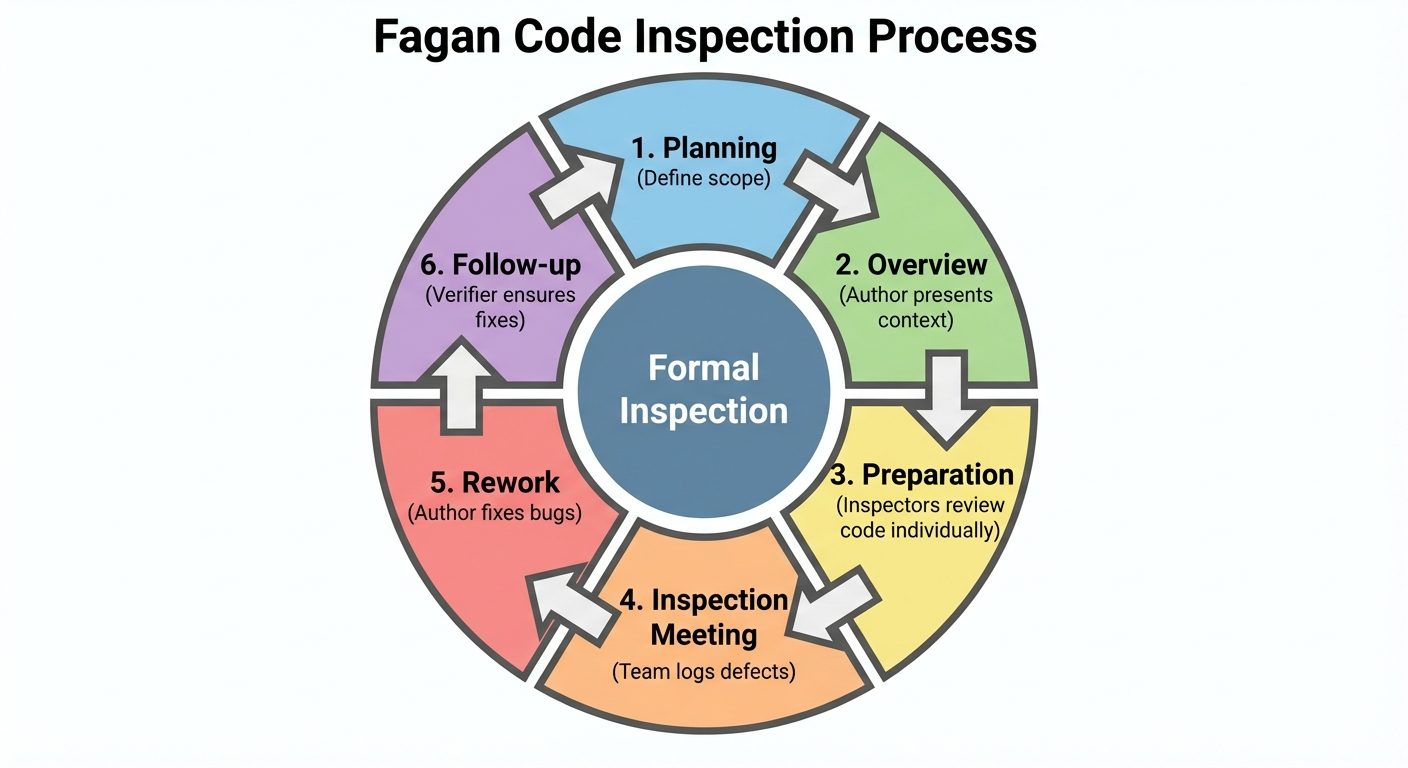
-
Code Inspection (Fagan Inspection):
- Type: Formal and rigorous.
- Roles: Moderator, Author, Reader, Recorder.
- Process: Checklists are used to find defects before the meeting. Metrics are collected.
- Goal: Defect removal.
-
Pair Programming:
- Type: Real-time continuous review.
- Process: Two developers work at one workstation. One writes (Driver), the other reviews (Navigator).
- Goal: Real-time quality assurance and problem-solving.