Unit 3 - Notes
Unit 3: Fiber Optics
1. Introduction to Fiber Optics
Fiber optics is a technology associated with the transmission of information as light pulses along a glass or plastic strand or fiber. Optical fibers carry much more information than conventional copper wire and are immune to electromagnetic interference.
Structure of an Optical Fiber
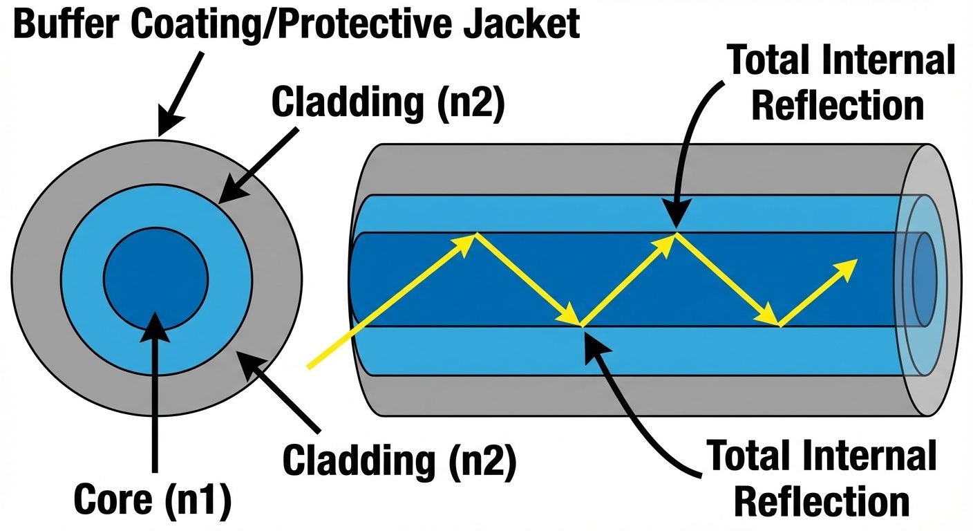
An optical fiber consists of three concentric cylindrical sections:
- Core: The innermost section made of glass or plastic with a high refractive index (). This is the medium through which light propagates.
- Cladding: The layer surrounding the core with a slightly lower refractive index (). It confines the light within the core.
- Buffer Coating (Jacket): The outermost plastic layer that protects the fiber from moisture, abrasion, and physical damage.
2. Optical Fiber as a Dielectric Waveguide
An optical fiber acts as a cylindrical dielectric waveguide that transmits light along its axis. It operates on the principle of electromagnetic wave propagation.
- It is termed "dielectric" because it is made of non-conducting materials (glass/silica).
- For the fiber to guide light, the refractive index of the core () must be greater than the refractive index of the cladding ().
- The cladding prevents light from leaking out and prevents cross-talk between adjacent fibers in a bundle.
3. Total Internal Reflection (TIR)
The fundamental principle behind fiber optic communication is Total Internal Reflection.
Conditions for TIR
- Light must travel from a denser medium (Core, ) to a rarer medium (Cladding, ). Therefore, .
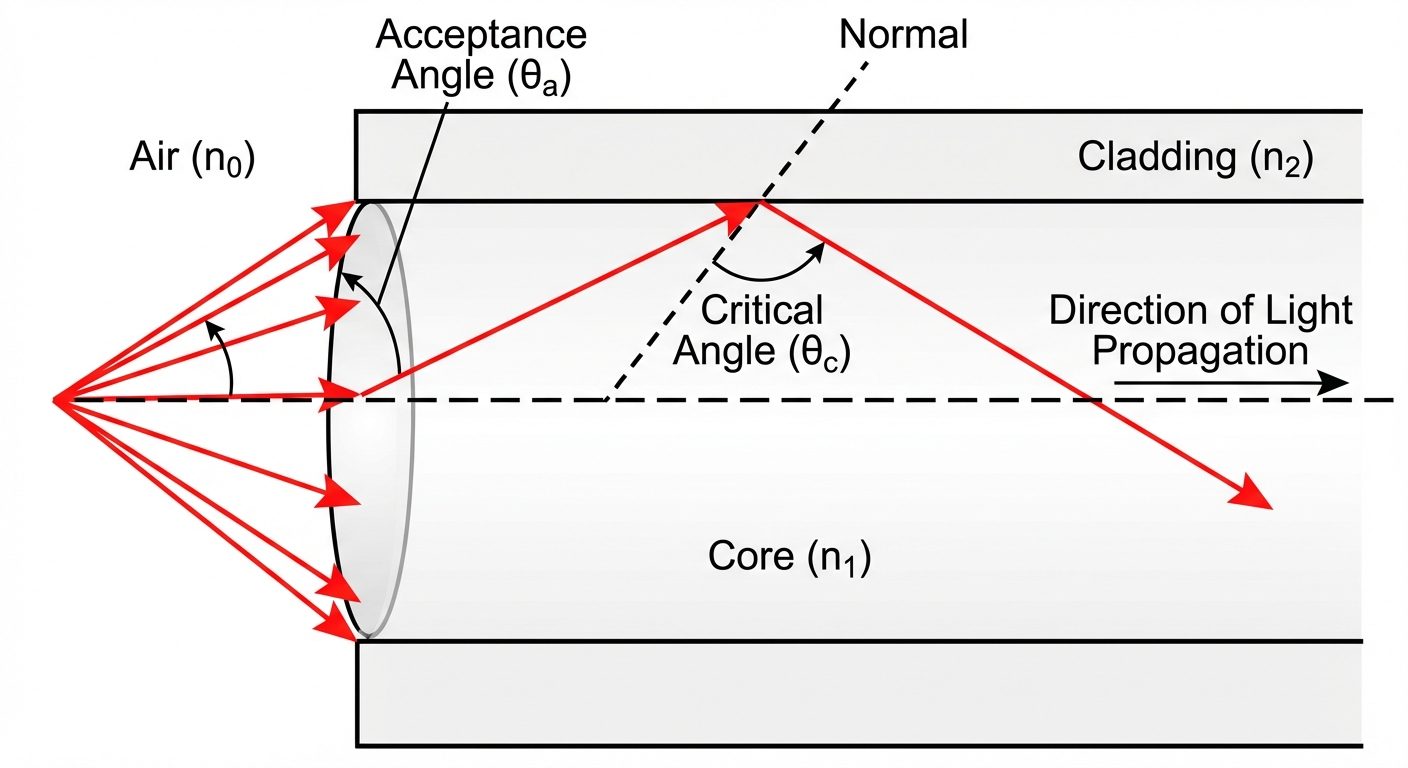
- The angle of incidence () at the core-cladding interface must be greater than the Critical Angle ().
Critical Angle ()
The critical angle is the angle of incidence for which the angle of refraction is (grazing the interface).
Using Snell's Law:
If the incidence angle , the ray is reflected back into the core with zero loss of energy.
4. Acceptance Angle ()
The acceptance angle is the maximum angle at the input end of the fiber (launching end) at which a light ray can enter the core and still undergo total internal reflection at the core-cladding interface.
- Any ray entering within this cone is guided through the fiber.
- Any ray entering outside this cone refracts into the cladding and is lost.
Formula:
Assuming the fiber is in air ():
5. Numerical Aperture (NA)
Numerical Aperture is a measure of the light-gathering ability of an optical fiber. It is a dimensionless quantity that describes the cone of acceptance.
- A higher NA indicates a larger acceptance angle, meaning the fiber can accept light from a wider angle (easier to couple light into).
- However, a very high NA can increase modal dispersion (pulse spreading).
Formula:
6. Relative Refractive Index Difference ()
This parameter represents the fractional difference between the refractive indices of the core and the cladding. It is usually a very small value (typically less than 0.01 or 1%).
Formula:
Relation between NA and :
7. V-Number (Normalized Frequency)
The V-number is a dimensionless parameter that determines the number of modes (paths) a fiber can support. It helps classify fibers as Single Mode or Multi Mode.
Formula:
Where:
- = Radius of the core
- = Wavelength of the light source
Classification based on V-number:
- Single Mode Fiber (SMF): If . Only the fundamental mode propagates.
- Multi Mode Fiber (MMF): If . Multiple modes propagate.
Total Number of Modes ():
For a Step Index Multi Mode fiber, the approximate number of modes is:
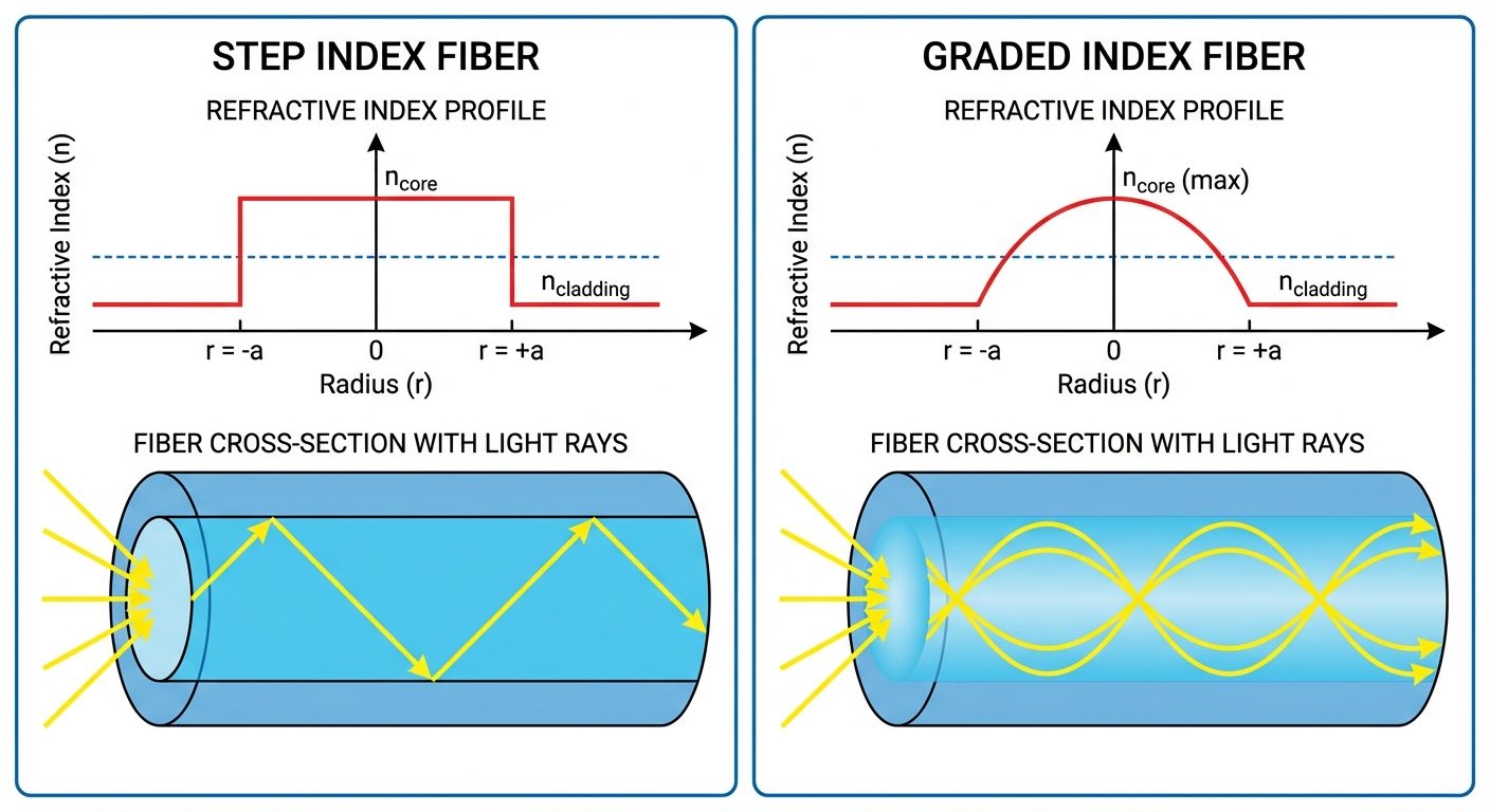
8. Types of Optical Fibers: Step Index and Graded Index
Optical fibers are classified based on the variation of the refractive index across the cross-section of the core.
A. Step Index Fiber
In a step index fiber, the refractive index of the core is uniform throughout and undergoes an abrupt change (step) at the core-cladding interface.
- Single Mode Step Index (SMSI):
- Very small core diameter ().
- Supports only one path of light.
- No intermodal dispersion. Used for long-distance communication.
- Multi Mode Step Index (MMSI):
- Larger core diameter ().
- Light travels in zig-zag paths.
- Suffers from Intermodal Dispersion (different rays take different times to travel), limiting bandwidth.
B. Graded Index Fiber (GRIN)
In a graded index fiber, the refractive index of the core is not uniform. It is maximum at the center (axis) and decreases gradually (parabolically) towards the cladding interface.
- Mechanism: Light rays traveling away from the axis move into lower refractive index regions, which increases their speed. This allows rays traveling longer paths (outer edges) to catch up with rays traveling shorter paths (axis).
- Path: Light travels in sinusoidal (helical) paths rather than zig-zag.
- Advantage: significantly reduces intermodal dispersion compared to MMSI fibers.
9. Losses Associated with Optical Fibers (Attenuation)
Attenuation is the reduction in signal strength (optical power) as light travels down the fiber. It is measured in decibels per kilometer (dB/km).
Formula:
Where is length in km, is input power, and is output power.
Main Types of Losses:
1. Absorption Losses
Caused by the material composition.
- Intrinsic Absorption: Caused by the interaction of light with the silica molecules themselves (UV and IR absorption bands).
- Extrinsic Absorption: Caused by impurities in the glass, specifically transition metal ions (Fe, Cr, Ni) and Hydroxyl ions () from water.
2. Scattering Losses
Caused by microscopic variations in material density and composition.
- Rayleigh Scattering: Occurs when light hits structural fluctuations smaller than the wavelength of light. The light scatters in all directions. This is the dominant loss mechanism at lower wavelengths.
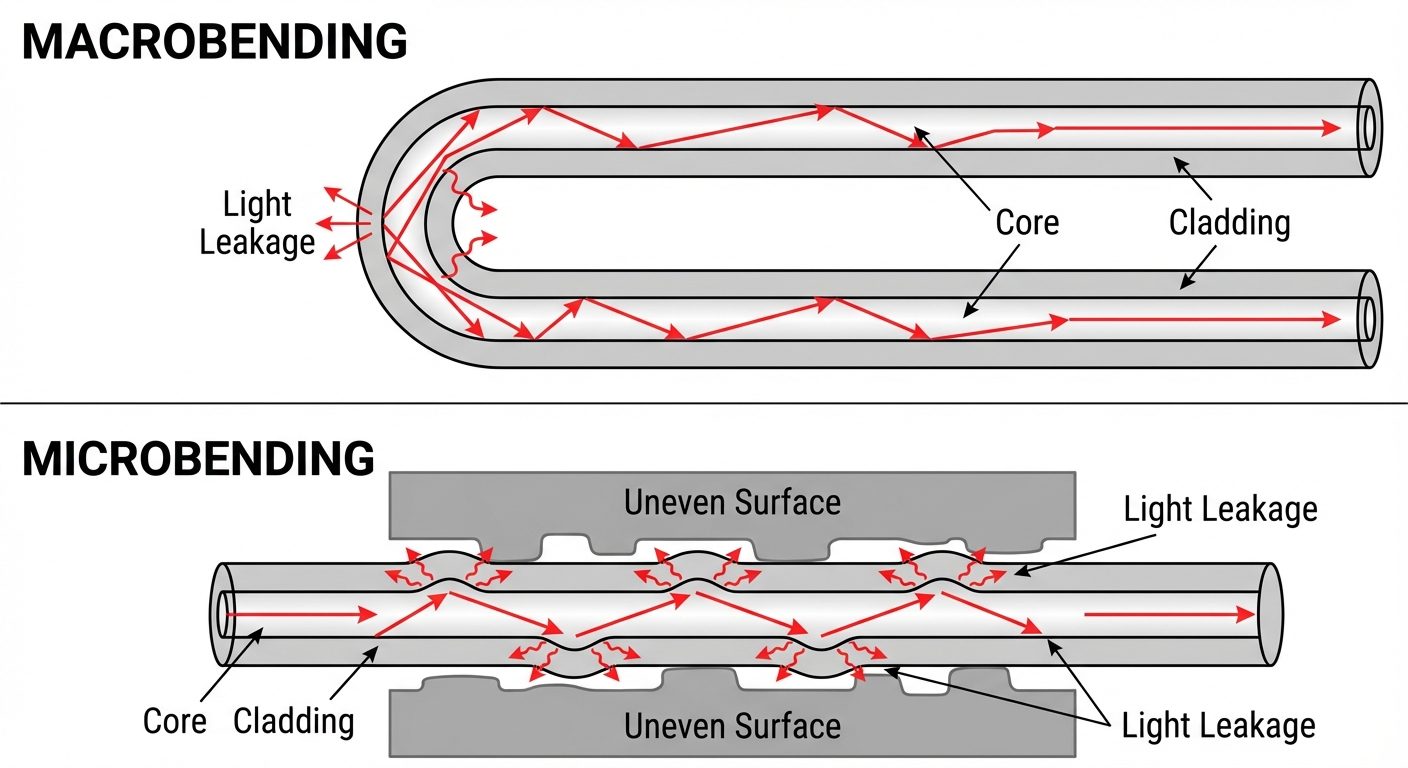
3. Bending Losses (Radiative Losses)
Occur when the fiber is bent, disrupting the condition for Total Internal Reflection.
- Macrobending: Occurs when the fiber is bent with a large radius of curvature (visible to the naked eye, e.g., wrapping fiber around a spool). Light strikes the interface at an angle less than the critical angle and leaks out.
- Microbending: Caused by microscopic imperfections or small bumps in the fiber geometry, often introduced during the cabling process. These micro-kinks cause mode coupling and leakage.