Unit 3 - Notes
Unit 3: Orthographic Projections
1. Introduction and Principles
Orthographic Projection is a method of representing three-dimensional objects on a two-dimensional plane. It is the universal language of engineering drawing, ensuring that distinct views of an object are projected onto planes perpendicular to each other.
The Principle of Projection
The theory relies on three distinct elements:
- The Object: The 3D item being drawn.
- The Observers (Projectors): Parallel lines of sight extending from the observer's eye (assumed to be at infinity) through the object.
- The Plane of Projection: The flat surface (paper or screen) where the image is captured.
In Orthographic projection, the projectors are perpendicular to the plane of projection and parallel to each other.
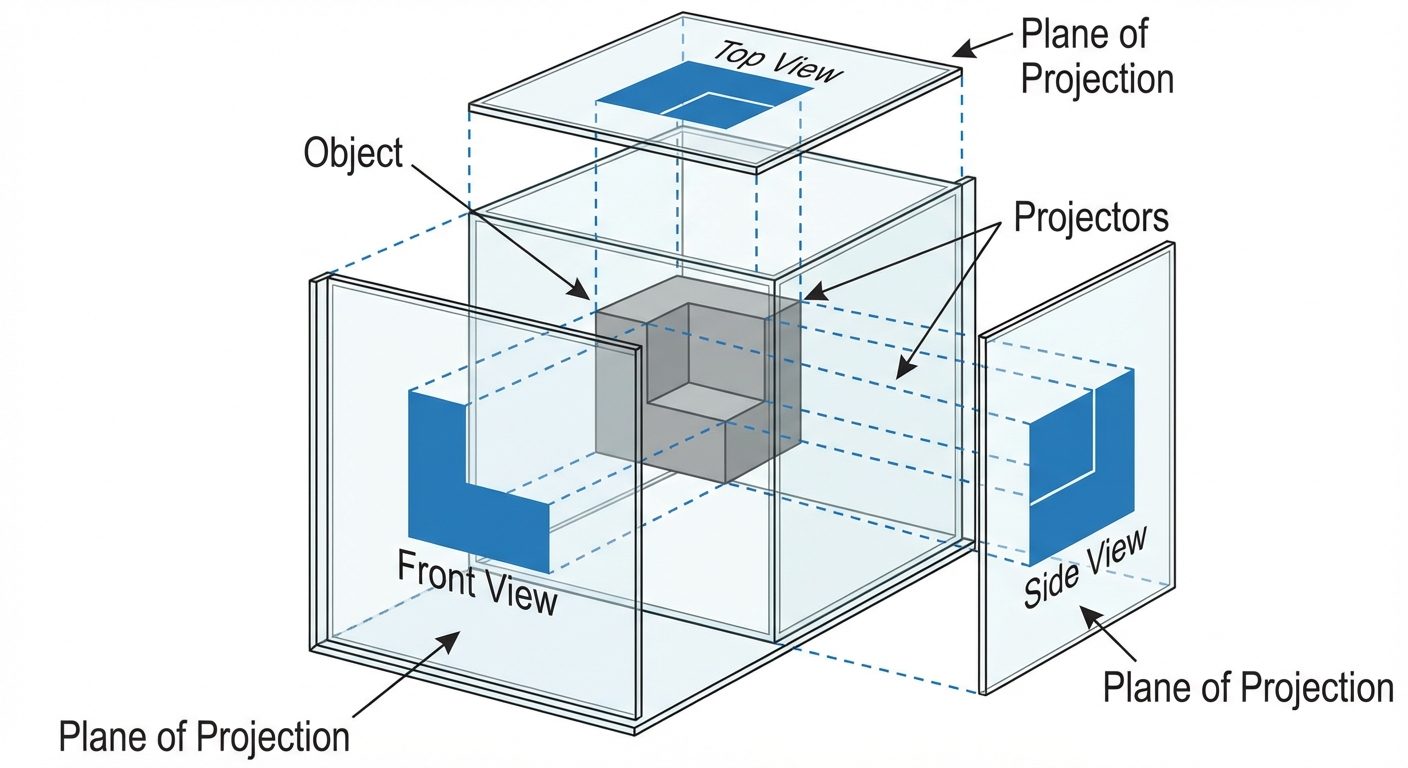
The "Glass Box" Concept
Imagine the object is suspended inside a transparent glass box. The observer looks perpendicular to each face of the box. The points on the object are projected onto the glass walls. When the glass box is unfolded onto a flat surface, the result is the set of orthographic views (Front, Top, and Side views).
2. Projection Systems: First Angle vs. Third Angle
The position of the object relative to the plane of projection and the observer defines the projection system. The space is divided into four quadrants (angles) by the intersection of the Vertical Plane (VP) and Horizontal Plane (HP).
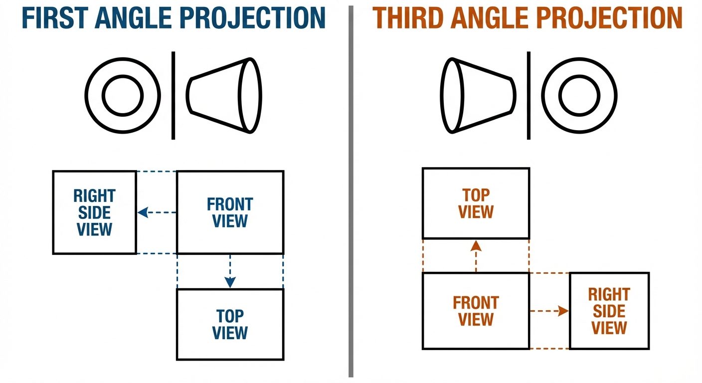
First Angle Projection (ISO Standard - Europe/Asia)
- Quadrant: The object is placed in the First Quadrant (above HP, in front of VP).
- Arrangement: Observer Object Plane.
- Resulting View Layout:
- Front View: Drawn above the XY reference line.
- Top View (Plan): Drawn below the Front View.
- Left Side View: Drawn to the right of the Front View.
- Right Side View: Drawn to the left of the Front View.
- Logic: The object is opaque; the image is projected onto the wall behind it.
Third Angle Projection (ANSI Standard - USA/Canada)
- Quadrant: The object is placed in the Third Quadrant (below HP, behind VP).
- Arrangement: Observer Plane Object.
- Resulting View Layout:
- Front View: Drawn below the XY reference line.
- Top View (Plan): Drawn above the Front View.
- Right Side View: Drawn to the right of the Front View.
- Logic: The plane is transparent; the observer sees the view through the plane.
3. AutoCAD Commands: Properties and Modification
Efficient drafting in AutoCAD requires mastery of object manipulation and property management.
Linetype and Properties
Technical drawings rely on line standards to convey meaning. In AutoCAD, these are managed via the Layer Properties Manager or the Properties Palette.
- Continuous (Thick): Visible outlines/edges (0.5mm - 0.7mm).
- Hidden (Dashed): Interior edges not visible from the outside (0.3mm).
- Center (Long-short-long): Center of circles, holes, and axes of symmetry.
- Phantom: Moving parts or alternate positions.
Command: LINETYPE (Load new linetypes) or LTSCALE (Adjust the spacing scale of dashed lines globally).
Modification Commands
These commands modify existing geometry. Most are found in the Modify panel of the Ribbon.
- Move (
M): Displaces objects a specified distance in a specified direction.- Step: Select Object Specify Base Point Specify Second Point.
- Copy (
COorCP): Creates duplicates of objects.- Step: Select Object Specify Base Point Specify Displacement. (Use "Multiple" mode for continuous copying).
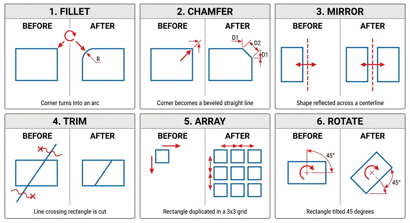
- Rotate (
RO): Revolves objects around a base point.- Step: Select Object Specify Base Point Enter Angle (Positive = Counter-Clockwise).
- Trim (
TR): Cuts objects to meet the edges of other objects.- Step: Select cutting edges (or press Enter to select all) Click segments to remove. Note: In newer AutoCAD versions, 'Quick Trim' is default.
- Erase (
E): Removes objects from the drawing database. - Mirror (
MI): Creates a reverse copy of the object across a defined axis.- Step: Select Object Define Mirror Line (2 points) Delete source object? (Yes/No).
- Scale (
SC): Enlarges or reduces objects proportionally.- Step: Select Object Base Point Scale Factor ( >1 enlarges, <1 reduces).
- Fillet (
F): Rounds and fillets the edges of objects.- Key Setting: Set Radius (
R) before selecting lines. - Step:
FREnter Radius Select two lines.
- Key Setting: Set Radius (
- Chamfer (
CHA): Bevels the edges of objects.- Key Setting: Distance (
D) or Angle (A). - Step:
CHADEnter Dist 1 Enter Dist 2 Select two lines.
- Key Setting: Distance (
- Array (
AR): Creates multiple copies of objects in a pattern.- Rectangular Array: Rows and Columns grid.
- Polar Array: Circular pattern around a center point.
- Path Array: Distributes items along a spline or line.
4. Hands-on Practice: Creating 2D Orthographic Drawings
This section outlines the workflow for converting a pictorial view (isometric) into orthographic views using AutoCAD.
Pre-requisites (Setup)
- Units: Type
UNSet to Millimeters or Inches. - Limits: Type
LIMITSSet lower left (0,0) and upper right (e.g., A4 size 297,210). - Layers: Create layers for 'Object Lines' (White/Thick), 'Hidden Lines' (Yellow/Dashed), 'Center Lines' (Red/Center), and 'Projection/Construction' (Grey/Thin).
Step-by-Step Workflow (Third Angle Example)
Step 1: Analysis
- Identify the most descriptive view to be the Front View (usually shows the length and height).
- Identify the Top View (shows length and depth).
- Identify the Side View (shows width and height).
Step 2: Construction Grid
- Draw a horizontal "X-line" (Infinite line) and a vertical X-line. These serve as the reference axes.
- Draw construction lines offset by 10-20mm from the main axes to create a gap between views.
Step 3: The Front View
- Switch to the 'Object Layer'.
- Using the
LINEcommand, draw the visible outline of the front view based on dimensions. - Use
FILLETorCHAMFERwhere necessary.
Step 4: The Top View
- Switch to 'Projection Layer'. Use
RAYorXLINEto project vertical lines up from the Front View corners into the Top View area. - Switch to 'Object Layer'. Draw horizontal lines representing the depth.
- Use
TRIMto clean up construction lines.
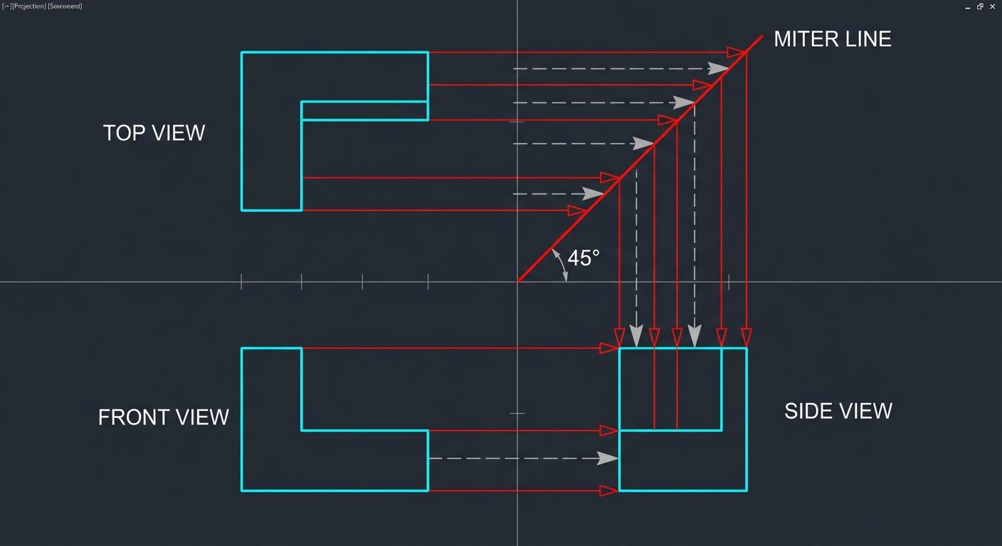
Step 5: The Side View (Using the Miter Line Method)
- From the intersection of the main reference axes, draw a line at 45 degrees into the projection quadrant (Top-Right for 3rd angle). This is the Miter Line.
- Project horizontal lines from the Top View to the Miter line.
- Where they intersect the Miter line, project them vertically down to the Side View area.
- Project horizontal lines from the Front View into the Side View area.
- The intersection of these projectors forms the Side View grid. Trace the object features.
Step 6: Final Details
- Hidden Details: Identify holes or slots not visible. Change layer to 'Hidden' and draw dashed lines.
- Center Lines: Mark circle centers and axes of symmetry.
- Dimensions: Use the
DIMLINEARandDIMRADIUScommands to annotate the drawing.