Unit 4 - Notes
Unit 4: Sectional Views
1. Introduction to Sectional Views
In engineering drawing, standard orthographic views (Front, Top, Side) use hidden (dashed) lines to represent internal features like holes, slots, and cavities. However, when an object has complex internal geometry, the abundance of hidden lines can make the drawing confusing and difficult to interpret.
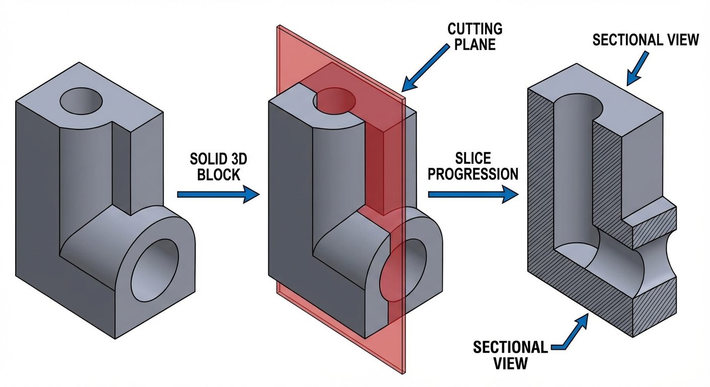
Definition: A Sectional View is a drawing view created by imagining the object being cut by a plane to reveal its internal details.
Purpose:
- To clarify internal details and reduce the confusion caused by hidden lines.
- To facilitate dimensioning of internal features.
- To clearly distinguish between solid material and void spaces.
2. Principle of Sectioning
The principle of sectioning involves an imaginary "Cutting Plane." Imagine a knife cutting through the object at a specific location. The piece of the object between the viewer and the cutting plane is removed.
Key Components:
- Cutting Plane Line: A thick line indicating where the imaginary cut is made. It usually consists of a long dash alternating with two short dashes (chain line), ending with arrows that indicate the direction of viewing.
- Section Lines (Hatching): Thin, continuous lines drawn at a 45° angle to indicate the surface where the material has been cut. Areas that are holes or voids are not hatched.
3. Types of Sectional Views
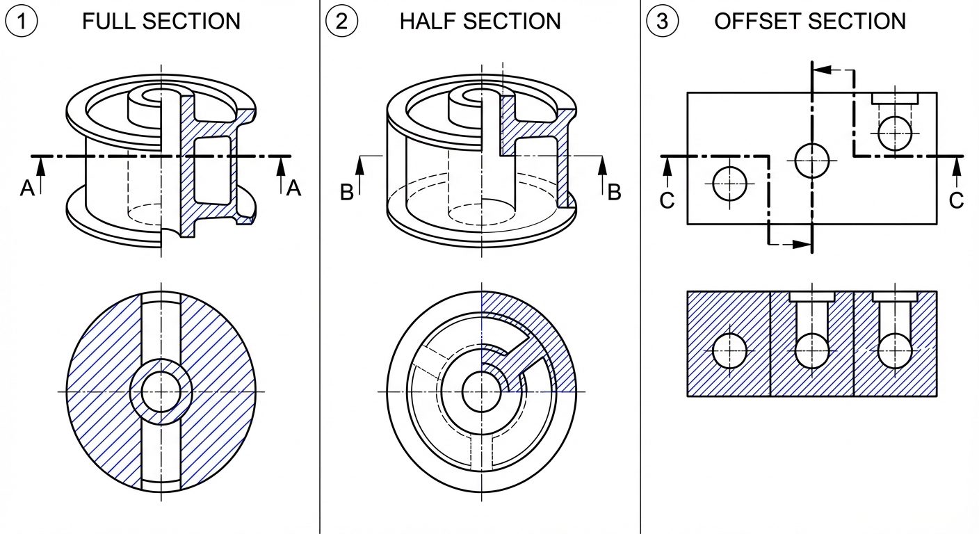
A. Full Section
A full section is created when the cutting plane passes entirely through the object in a straight line, splitting it into two equal or unequal halves.
- Usage: Best for objects where internal details are located along a central axis.
- Representation: The view replaces the standard exterior view.
B. Half Section
A half section is created by passing two cutting planes at right angles to each other along the center lines. Effectively, one-quarter of the object is removed.
- Usage: Ideal for symmetrical objects (like cylinders or pulleys).
- Representation: One half of the view is drawn in section (showing interior), and the other half is drawn as an exterior view.
- Note: Hidden lines are usually omitted in the un-sectioned half. The division line between the sectioned and un-sectioned half is a center line, not a solid line.
C. Offset Section
An offset section is used when internal features are not in a straight line. The cutting plane "steps" or bends to pass through features that are offset from the main center line.
- Usage: Complex parts with holes located at different depths or positions.
- Representation: The bends in the cutting plane are not shown in the final sectional view; the view appears as if the features were all on one plane.
4. First and Third Angle Projection in Sectioning
The rules of sectioning apply identically to both projection systems, but the placement of the views differs.
- First Angle Projection (Europe/Asia): The object is imagined to be in the first quadrant. The view is projected onto the plane behind the object.
- Placement: If the Cutting Plane is on the Front View, and arrows point down, the Sectional Top View is drawn below the Front View.
- Third Angle Projection (USA): The object is imagined to be in the third quadrant. The projection plane is between the observer and the object.
- Placement: If the Cutting Plane is on the Top View, and arrows point toward the front, the Sectional Front View is drawn below the Top View.
Crucial Rule: The arrows on the cutting plane line always indicate the direction of sight. You draw what remains behind the arrows.
5. AutoCAD Commands: Modification & Creation Tools
To create accurate sectional views, one must master specific modification tools to manipulate the geometry before applying hatching.
STRETCH
Used to elongate or shrink objects while maintaining connectivity.
- Command:
STRETCH(Shortcut:S) - Procedure: Select objects using a Crossing Window (green window, right-to-left). Only points inside the window move; points outside remain fixed.
- Application: Changing the length of a shaft without redrawing the ends.
EXPLODE
Breaks a compound object (like a Block, Polyline, or Hatch) into its constituent component objects (lines and arcs).
- Command:
EXPLODE(Shortcut:X) - Application: Modifying a rectangle drawn as a polyline into four separate lines to offset just one side.
OFFSET
Creates concentric circles, parallel lines, or parallel curves.
- Command:
OFFSET(Shortcut:O) - Procedure: Specify distance Select object Click on side to offset.
- Application: Creating walls of a pipe or thickness of a casing.
EXTEND
Lengthens a line or arc to meet another object (boundary edge).
- Command:
EXTEND(Shortcut:EX) - Procedure: Select boundary object Enter Select line to extend.
JOIN
Combines similar objects (like collinear lines or arcs) into a single object.
- Command:
JOIN(Shortcut:J) - Application: Fixing gaps in lines before hatching (Hatching requires closed boundaries).
REGION
Converts objects that enclose an area into a 2D region object (a plane).
- Command:
REGION(Shortcut:REG) - Application: Used for calculating area/centroid properties or preparing for 3D modeling.
BREAK
Creates a gap in an object or breaks it into two points.
- Command:
BREAK(Shortcut:BR) - Application: Removing a segment of a line where a component intersects.
6. AutoCAD Commands: Hatching
Hatching is the specific command used to generate the diagonal section lines required for sectional views.
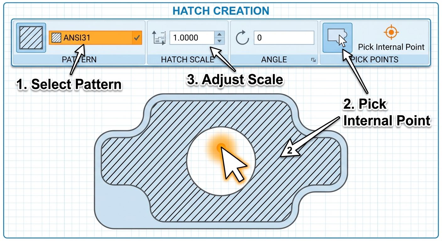
HATCH Command
Fills an enclosed area or selected objects with a hatch pattern, solid fill, or gradient.
- Command:
HATCH(Shortcut:H) - The Ribbon Context Tab: When
His typed, the ribbon changes to "Hatch Creation."
Key Settings:
- Pattern: The standard engineering pattern for cast iron or general use is ANSI31 (diagonal lines).
- Scale: Adjusts the spacing of the lines. If lines look solid, increase scale. If lines don't appear, decrease scale.
- Angle: Rotates the pattern (default is 45° for ANSI31).
- Pick Points vs. Select Objects:
- Pick Points: Click inside a closed area (AutoCAD calculates the boundary).
- Select Objects: Click the specific boundary lines.
HATCHEDIT Command
Used to modify an existing hatch without deleting and redrawing it.
- Command:
HATCHEDIT(Shortcut:HE) - Procedure: Type
HEClick the hatch. A dialog box appears allowing changes to pattern, scale, or angle.
7. Hands-on Practice: Creating a 2D Sectional View
Follow this workflow to create a Sectional Front View from a given object.
Step 1: Prepare the Geometry
- Set units (
UN) to Millimeters. - Use layers: Create layers for Visible Lines (White/Continuous), Center Lines (Yellow/Center), and Hatching (Red/Continuous).
- Draw the Top View and Front View outline using
LINE,CIRCLE, andOFFSET.
Step 2: Define the Cut
- On the Top View, draw the Cutting Plane Line passing through the center.
- Identify which portion of the object is removed (the portion closest to the observer).
Step 3: Modify the Front View
- Project lines from the cut features in the Top View down to the Front View using
RAYorXLINE. - Use
TRIMto remove lines that represent the exterior shell that has been "cut away." - Change hidden lines (dashed) that are now exposed to visible lines (continuous).
Step 4: Apply Hatching
- Switch to the Hatching layer.
- Type
H(Enter). - Select Pattern: ANSI31.
- Scale: Set to 1.0 (adjust to 2.0 or 0.5 if spacing is too tight/loose).
- Click inside the solid walls of the object in the Front View.
- Note: Do not hatch ribs/webs if the cut is along their length (longitudinal).
- Note: Do not hatch holes or shafts/fasteners (bolts, nuts) even if cut.
- Press Enter to close.
Step 5: Finalize
- Use
DIMto add dimensions. - Use
MTEXTto label the view "SECTION A-A".