Unit 2 - Notes
Unit 2: Projection of Points and Lines
1. Introduction to Orthographic Projections
Orthographic Projection is a technical drawing method where a 3D object is represented in 2D views by projecting its points perpendicular to projection planes.
Key Concepts:
- Principal Planes:
- Vertical Plane (VP): The plane placed vertically in front of the observer. The view obtained on the VP is called the Front View (FV) or Elevation.
- Horizontal Plane (HP): The plane placed horizontally. The view obtained on the HP is called the Top View (TV) or Plan.
- Reference Line (XY Line): The line of intersection between the HP and VP.
- Auxiliary Planes: Profile Plane (PP) used for Side Views.
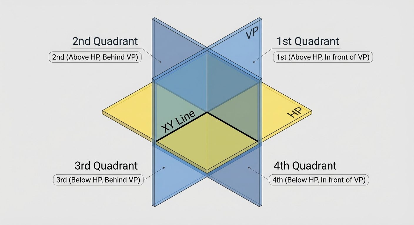
Principles of Quadrants
The intersection of the VP and HP creates four quadrants. The position of an object is defined relative to these planes.
Comparison of Projection Systems
| Feature | First Angle Projection | Third Angle Projection |
|---|---|---|
| Object Position | First Quadrant (Above HP, In front of VP) | Third Quadrant (Below HP, Behind VP) |
| Observer Logic | Observer -> Object -> Plane | Observer -> Plane -> Object |
| View Position | Top View is below the XY line; Front View is above. | Top View is above the XY line; Front View is below. |
| Usage | Standard in India/Europe (ISO) | Standard in USA |
2. Orthographic Projection of Points
A point has no dimensions but has a specific position in space.
Standard Notation:
- Actual Point: Capital Letter (e.g., A)
- Front View (on VP): Lowercase with a dash (e.g., a')
- Top View (on HP): Lowercase (e.g., a)
Rules for Projection of Points
- Point in 1st Quadrant:
- a' is above XY.
- a is below XY.
- Point in 2nd Quadrant:
- a' is above XY.
- a is above XY. (Both views overlap or lie above the reference line).
- Point in 3rd Quadrant:
- a' is below XY.
- a is above XY.
- Point in 4th Quadrant:
- a' is below XY.
- a is below XY.
3. Projection of Lines
A line is defined by the shortest distance between two points. The projection depends on the line's orientation relative to the HP and VP.
Fundamental Cases
1. Line Parallel to Both HP and VP
- Front View: Parallel to XY line. True Length (TL).
- Top View: Parallel to XY line. True Length (TL).
2. Line Perpendicular to One Plane and Parallel to the Other
- Perpendicular to HP (Parallel to VP):
- FV: A vertical line perpendicular to XY (True Length).
- TV: A point.
- Perpendicular to VP (Parallel to HP):
- FV: A point.
- TV: A vertical line perpendicular to XY (True Length).
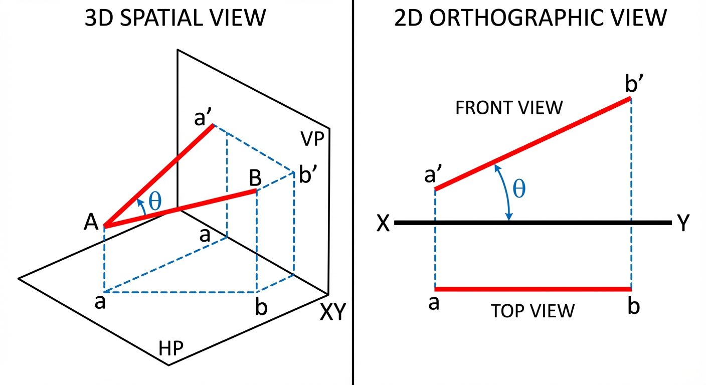
3. Line Inclined to One Plane and Parallel to the Other
- Inclined to HP and Parallel to VP:
- FV: Inclined line showing True Length and True Inclination ().
- TV: A horizontal line parallel to XY (Apparent Length / Shorter).
- Inclined to VP and Parallel to HP:
- FV: A horizontal line parallel to XY (Apparent Length).
- TV: Inclined line showing True Length and True Inclination ().
4. Line Inclined to Both Planes
- Neither view shows the True Length or True Inclinations directly.
- Requires the Rotating Line Method or Trapezoidal Method to find true lengths.
- Apparent Angles: (Front View inclination) and (Top View inclination).
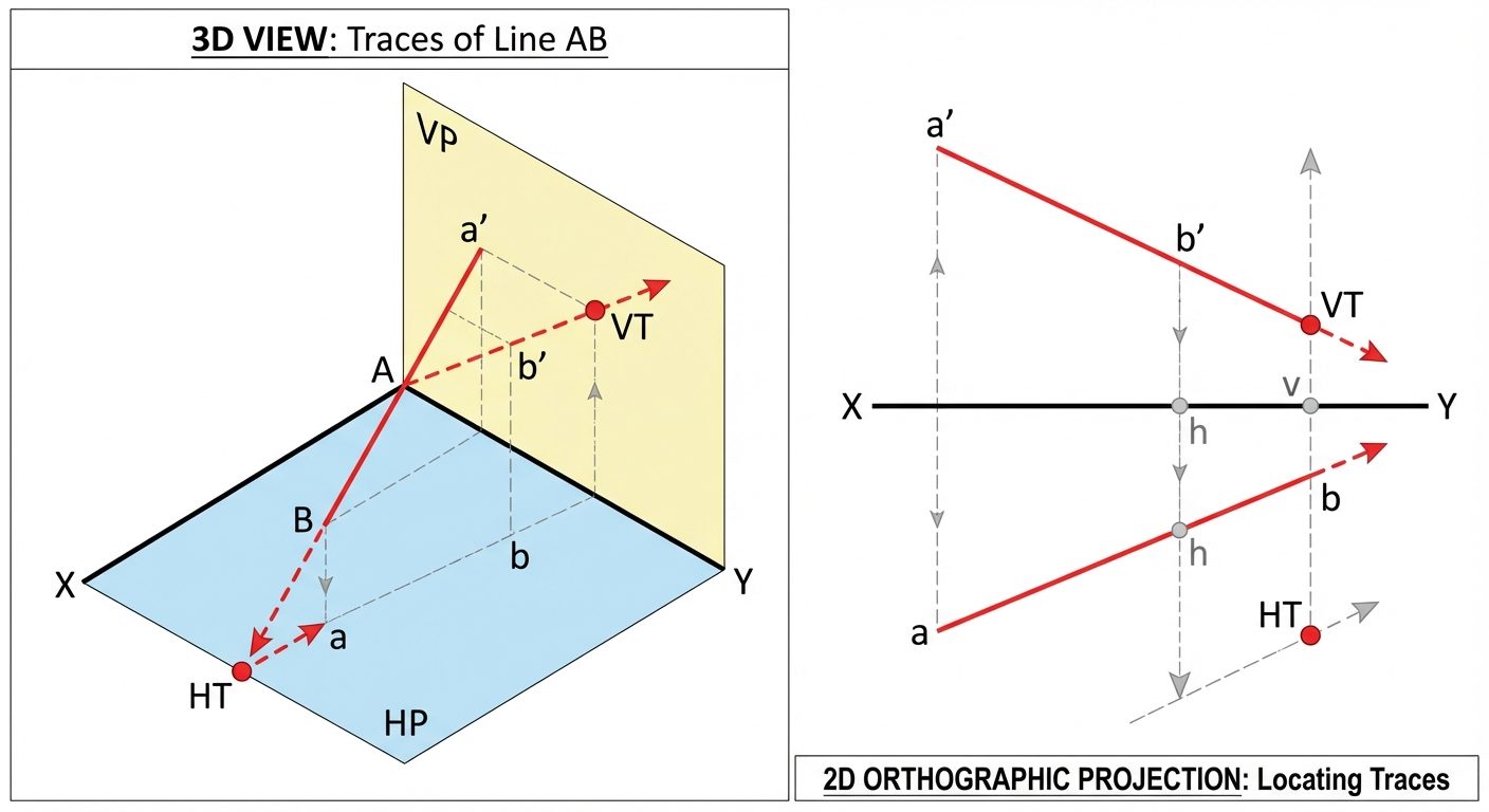
Concept of Traces
Traces are the points where a line (extended if necessary) meets the reference planes.
- Horizontal Trace (HT): The point where the line intersects the Horizontal Plane. In the Front View, the line must be extended to meet the XY line to locate the HT position.
- Vertical Trace (VT): The point where the line intersects the Vertical Plane. In the Top View, the line must be extended to meet the XY line to locate the VT position.
4. AutoCAD Commands for Engineering Drawing
AutoCAD (Computer-Aided Design) replaces manual drafting tools. Below are essential commands for projecting points and lines.
Basic Draw Commands
1. Line
Creates straight line segments.
- Command:
LINEorL - Steps:
- Type
L> Enter. - Specify first point (click or enter coordinates
X,Y). - Specify next point (or enter
@length<anglefor polar coordinates).
- Type
- Ortho Mode (F8): Toggles strictly horizontal/vertical drawing (essential for projectors).
2. Circle
Creates circles based on radius or diameter.
- Command:
CIRCLEorC - Steps:
- Type
C> Enter. - Click center point.
- Type radius value > Enter.
- Type
3. Arc
Creates curved segments.
- Command:
ARCorA - Common Method (3-Point): Specify Start, Second point, End.
- Engineering Method: Start, Center, End (useful for rotating lines to find true length).
4. Polyline
Creates a single object composed of continuous line and arc segments.
- Command:
PLINEorPL - Difference from Line: A rectangle made with Lines consists of 4 objects; a rectangle made with Polyline is 1 object.
Geometric Shapes
1. Rectangle
- Command:
RECTANGorREC - Steps: Specify first corner, then specify opposite corner (or dimensions).
2. Polygon
Creates regular polygons (equilateral triangle, square, pentagon, hexagon, etc.).
- Command:
POLYGONorPOL - Steps:
- Enter number of sides (e.g., 6 for hexagon).
- Specify center.
- Choose Inscribed in circle (vertex touches circle) or Circumscribed about circle (midpoint of edge touches circle).
3. Ellipse
Used for isometric circles or projections of inclined circles.
- Command:
ELLIPSEorEL - Methods:
- Center: Specify center and two axis endpoints.
- Axis, End: Specify one axis length and half the other axis length.
Dimensioning and Annotation
Dimension Style Manager
Controls the appearance of dimensions (text height, arrow size, precision).
- Command:
DIMSTYLEorD - Key Settings:
- Lines: Color, lineweight.
- Symbols and Arrows: Arrowhead type (Closed Filled for engineering).
- Text: Height (usually 2.5mm or 3mm), placement (Above/Centered).
- Primary Units: Precision (0.00).
Dimension Commands
DIMLINEAR(DLI): Linear dimensions (horizontal/vertical).DIMALIGNED(DAL): Dimensions for inclined lines (True Length).DIMANGULAR(DAN): Measures angles.
5. Hands-on Practice: AutoCAD Workflow
To solve a problem of Projection of Lines in AutoCAD, follow this workflow:
-
Setup:
- Turn on Grid (F7) and Snap (F9) if needed.
- Enable Object Snap (F3) (Endpoint, Midpoint, Intersection) for accuracy.
- Enable Ortho Mode (F8) for straight projection lines.
-
Draw XY Line:
- Use
Lcommand. Draw a horizontal line. Change properties (Color: Red, Linetype: Continuous).
- Use
-
Draw Projections (Example: Line Inclined to HP):
- Identify position of point A (e.g., 20mm above HP). Use
OFFSETcommand from XY line. - Draw the Front View (a'b') using Polar Coordinates (
@Length<Angle). - Draw Projectors: Draw vertical lines from a' and b' downwards past XY using Ortho mode.
- Draw Top View: Connect the intersection points.
- Identify position of point A (e.g., 20mm above HP). Use
-
Dimensioning:
- Use
DALfor true length. - Use
DANfor inclination angles. - Use
DLIfor distances from HP/VP.
- Use
-
Finalizing:
- Use Layers: Create layers for 'Object Lines' (Thick, White), 'Projectors' (Thin, Grey), and 'Dimensions' (Green).