Unit 1 - Notes
Unit 1: Introduction to Engineering Drawing
1. Conceptual Framework of Drawing Instruments
Engineering drawing is the universal language of engineers. Precision and standardization depend heavily on the correct usage of drawing instruments.
Key Instruments and Their Uses
- Drawing Board: Provides a smooth, flat surface. Usually made of soft wood (like seasoned pine) to hold paper clips or tape.
- Mini-Drafter (or T-Square):
- T-Square: Used for drawing horizontal lines and supporting set squares.
- Mini-Drafter: Combines the functions of a T-square, set squares, scale, and protractor. It uses a parallelogram mechanism to keep the ruling edge parallel to a reference anywhere on the board.
- Set Squares: Used in conjunction with a T-square or clamped drafter.
- Set Square: Draws , , and lines.
- Set Square: Draws , , , , and lines.
- Instrument Box:
- Compass: Large compass with a knee joint for drawing circles mm radius; Bow compass for small circles.
- Dividers: Used to transfer dimensions from scale to paper or to divide lines into equal parts.
- Pencils (Grades of Lead):
- Hard Grades (4H to 6H): Used for very light construction lines, center lines, and guide lines. The clay content is higher.
- Medium Grades (H, 2H): Used for object lines, lettering, and dimensioning.
- Soft Grades (HB, B): Used for artistic sketching or freehand work (rarely used in precision engineering drawing except for boundaries).
- French Curves: Used to draw smooth curves (ellipses, parabolas, hyperbolas) that cannot be drawn with a compass.
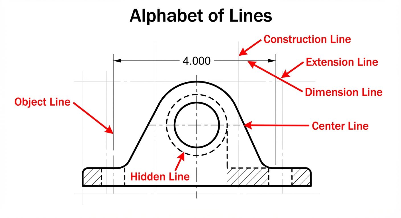
2. Line Types (The Alphabet of Lines)
Standardization of lines is defined by ISO and ANSI standards. Line thickness and style convey specific meanings about the geometry of the object.
| Line Type | Representation | Description | Pencil Grade |
|---|---|---|---|
| Object / Visible Line | _________ |
Continuous thick line. Represents visible edges and outlines. | H or HB |
| Hidden Line | _ _ _ _ _ |
Dashed medium line. Represents interior edges not visible from the outside. | 2H |
| Center Line | __ _ __ _ |
Long dash followed by a short dash (chain line). Indicates axes of symmetry or centers of circles. | 4H |
| Construction Line | _________ |
Continuous very thin line. Used for initial layout and guides. | 4H or 6H |
| Dimension/Extension | |<--10-->| |
Continuous thin line. Defines the start and end of a measurement. | 2H |
| Cutting Plane Line | __ _ _ __ |
Thick chain line with thickened ends. Shows where an object is hypothetically cut. | H |
3. Dimensioning
Dimensioning is the process of defining the size, form, and location of geometric features.
Components of a Dimension
- Extension Line: Thin continuous line extending from the object to indicate the limit of the dimension. A gap of 1mm is left between the object and the extension line.
- Dimension Line: Thin continuous line drawn parallel to the measurement, terminated by arrowheads.
- Arrowheads: Standard ratio of Length to Width is 3:1. They must be filled and sharp.
- Leader Line: A thin line leading from a note or dimension to a feature (usually a hole), terminating in a dot or arrowhead.
Systems of Dimensioning
- Aligned System: Dimensions are placed perpendicular to the dimension line. They are readable from the bottom or the right-hand side of the drawing.
- Unidirectional System: Dimensions are placed vertically so they can be read from the bottom of the drawing sheet only. The dimension line is broken in the middle to insert the text.
4. Single Stroke Vertical Gothic Lettering
Lettering must be legible, uniform, and suitable for microfilming/digitization. "Single stroke" means the thickness of the letter is obtained in one stroke of the pencil/pen.
Guidelines
- Aspect Ratio: Standard height-to-width ratio is often 7:4 (Height:Width) for most letters, though 'M' and 'W' are usually 7:5 or 7:6, and 'I' is just a stroke.
- Capitalization: Engineering drawings predominantly use all UPPERCASE letters.
- Stability: Letters like B, E, H, S should appear stable; the middle horizontal stroke is often drawn slightly above the visual center.
- Spacing:
- Space between letters: 1/5th of height.
- Space between words: 1 height.
- Space between lines: 1/2 to 1 height.
5. Scales
Scales allow large objects (buildings) or small objects (watch gears) to be represented on standard paper sizes.
Representative Fraction (R.F.):
- Full Scale (1:1): Drawing size equals actual size.
- Reducing Scale (1:X): Drawing is smaller (e.g., 1:10, 1:50).
- Enlarging Scale (X:1): Drawing is larger (e.g., 2:1, 5:1).
Plain Scale
A plain scale represents two units (e.g., Kilometers and Hectometers) or a unit and its first subdivision.
- It consists of a line divided into a specific number of equal main parts.
- The first main division (on the left) is subdivided into smaller parts to read fractions of the main unit.
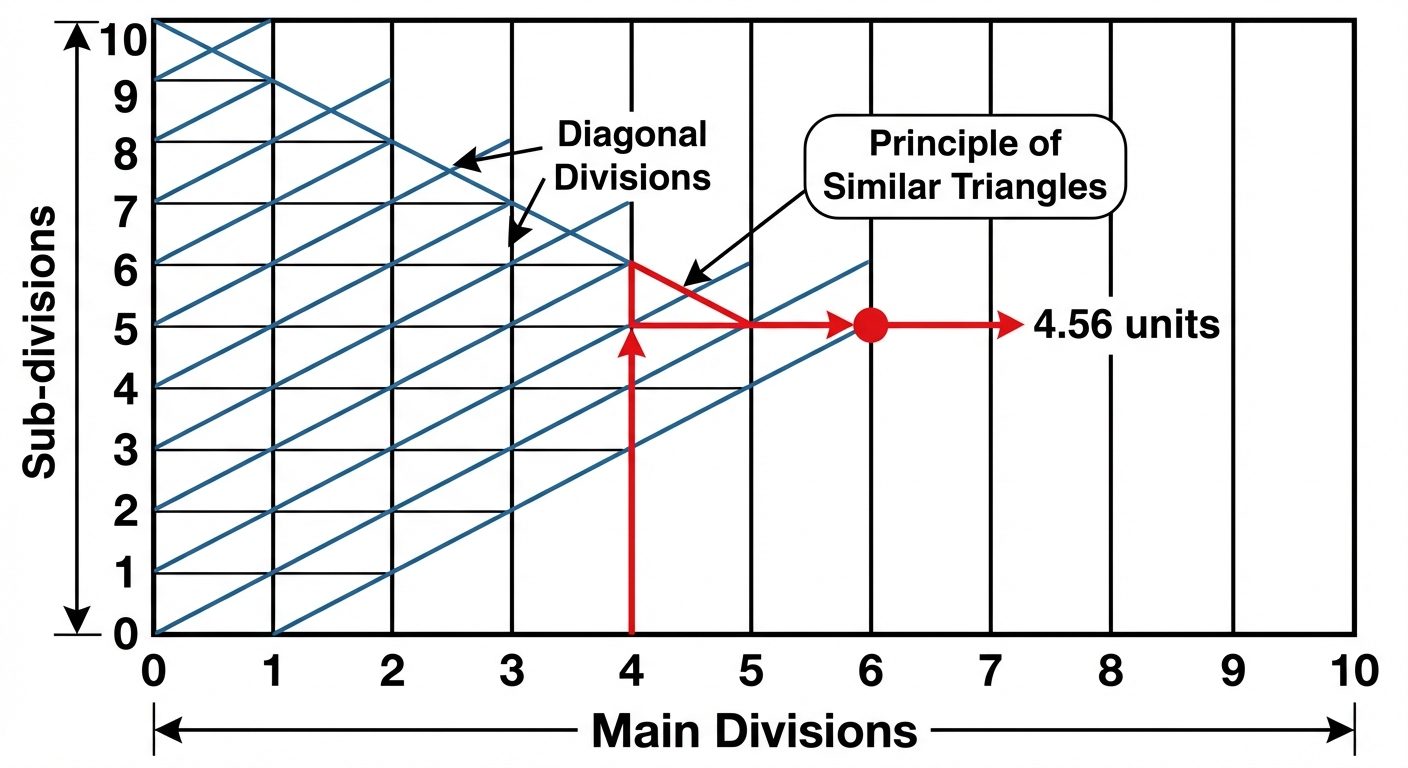
Diagonal Scale
A diagonal scale is used when very minute measurements are required or to measure three consecutive units (e.g., Meters, Decimeters, and Centimeters) or up to two decimal places.
- Principle: It relies on the principle of similar triangles. To divide a short vertical line into equal parts, a diagonal line is drawn across horizontal parallels.
6. Introduction to AutoCAD Interface
AutoCAD (Computer-Aided Design) replaces manual drafting tools with digital precision.
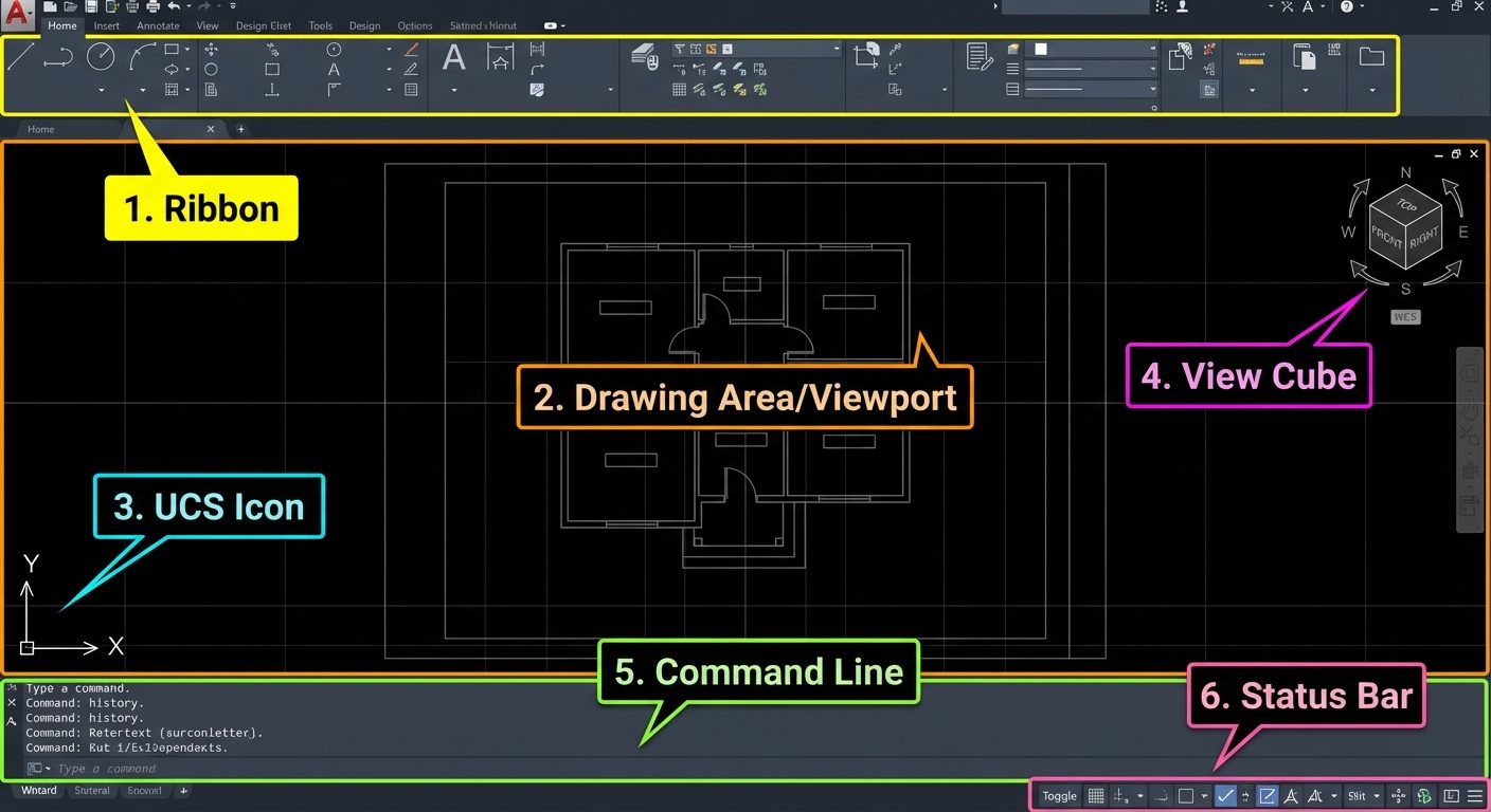
The Interface Layout
- Application Menu (Big Red A): File management (New, Open, Save, Print).
- Ribbon: Organized tabs (Home, Insert, Annotate) containing panels of tools (Draw, Modify, Layers).
- Drawing Area (Viewport): Infinite space where drawing occurs.
- UCS Icon: Visual indicator of X and Y axes.
- Command Line: The primary method for communicating with AutoCAD (typing commands).
- Status Bar: Toggles for drawing aids (Grid, Snap, Ortho) located at the bottom right.
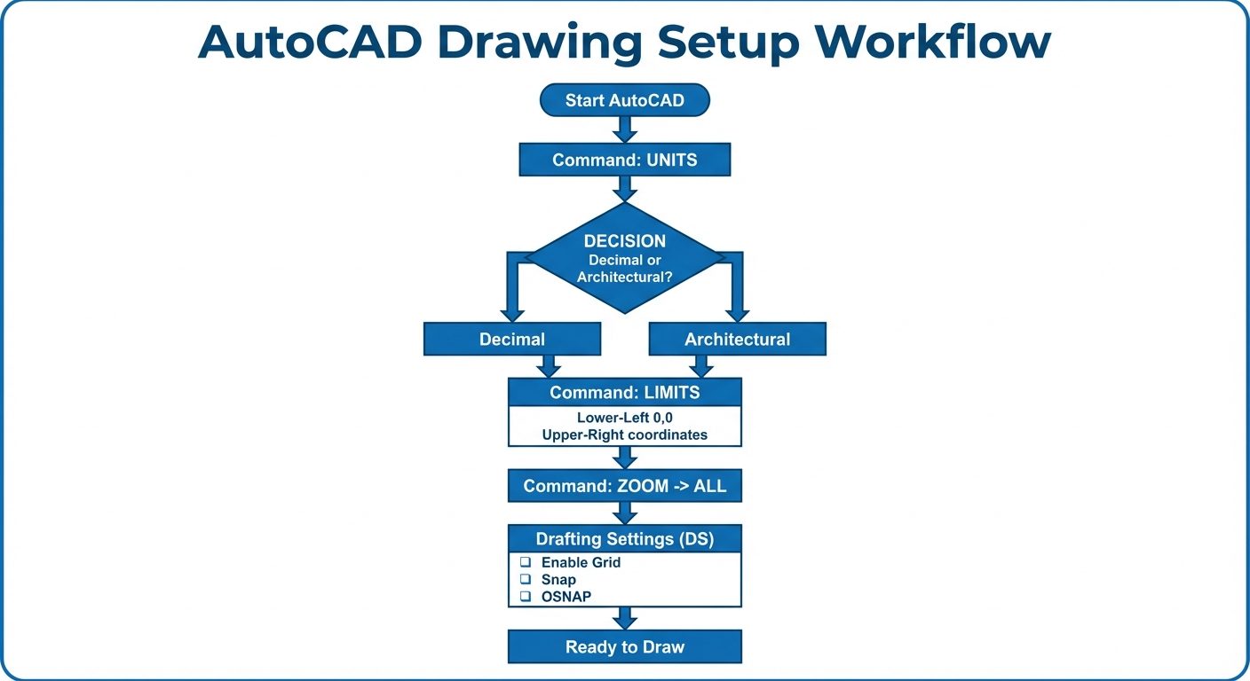
Essential Setup Commands
1. UNITS (UN + Enter)
Defines the precision and type of measurement.
- Type: Decimal (Mechanical), Architectural (Feet/Inches).
- Precision: Number of decimal places (e.g., 0.00).
- Insertion Scale: Unit for content inserted from other drawings (Millimeters/Inches).
2. LIMITS (LIMITS + Enter)
Sets the invisible boundary of the drawing area (equivalent to paper size).
- Specify lower-left corner: Usually
0,0. - Specify upper-right corner: Usually matches paper size (e.g., A4:
210,297). Z(Zoom)A(All) is required to refresh the screen to these limits.
Navigation Tools
- Pan (
P): Holding the middle mouse button moves the view without changing coordinates. - Zoom (
Z): Magnifies or shrinks the view.- Zoom Extents: Shows all drawn objects.
- Zoom Window: Zooms into a user-defined rectangle.
- Mouse Scroll: Roll forward to zoom in, backward to zoom out.
Drawing Aids (Status Bar & F-Keys)
OSNAP (Object Snap - F3)
Allows the cursor to snap precisely to geometric points rather than estimating.
- Endpoint: Square icon (ends of lines).
- Midpoint: Triangle icon (center of a line).
- Center: Circle icon (center of arc/circle).
- Intersection: X icon (where objects cross).
- Note: Can be configured via
DS(Drafting Settings).
ORTHO Mode (F8)
Restricts cursor movement to horizontal () and vertical () axes. Essential for drawing straight projection lines.
UCS (User Coordinate System)
- WCS (World Coordinate System): The fixed, default system where is permanent.
- UCS: A movable system defined by the user to simplify drawing on angled faces or different planes in 3D.
Function Key Cheat Sheet
| Key | Function | Description |
|---|---|---|
| F1 | Help | Opens Autodesk help documentation. |
| F2 | Text Screen | Expands the command history window. |
| F3 | OSNAP | Toggles Object Snap on/off. |
| F7 | Grid | Toggles the background grid visibility. |
| F8 | ORTHO | Toggles Orthogonal mode (Straight lines only). |
| F9 | Snap Mode | Snaps cursor to grid points. |
| F10 | Polar Tracking | Restricts cursor to specified angles (e.g., every ). |
| F12 | Dynamic Input | Displays coordinates and prompts near the cursor. |