Unit 3 - Notes
Unit 3: Fiber Optics
1. Introduction to Fiber Optics
Fiber optics is a technology associated with the transmission of information as light pulses along a glass or plastic strand or fiber. A fiber optic cable can contain a varying number of these glass fibers, from a few up to a couple of hundred. Another glass layer, called cladding, surrounds the glass fiber core.
Key Characteristics:
- Bandwidth: Extremely high information-carrying capacity.
- Immunity: Immune to Electromagnetic Interference (EMI) and Radio Frequency Interference (RFI).
- Security: Difficult to tap without detection.
- Loss: Very low signal attenuation compared to copper wires.
2. Optical Fiber as a Dielectric Waveguide
An optical fiber is essentially a cylindrical dielectric waveguide that acts as a conduit for electromagnetic radiation at optical frequencies.
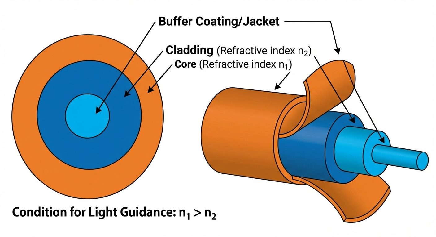
Structure of an Optical Fiber
- Core: The central region of the fiber through which light is transmitted. It has a refractive index . Typical diameter ranges from to .
- Cladding: The material surrounding the core. It has a refractive index , where . This difference is critical for maintaining light within the core.
- Buffer Coating (Jacket): A protective plastic coating (often acrylate) that protects the fiber from moisture and physical damage.
3. Principle of Operation: Total Internal Reflection (TIR)
Light travels in the optical fiber based on the principle of Total Internal Reflection (TIR).
Conditions for TIR:
- Light must travel from a medium of higher refractive index (Core, ) to a medium of lower refractive index (Cladding, ).
- The angle of incidence () at the core-cladding interface must be greater than the Critical Angle ().
The Critical Angle ()
From Snell's Law: .
At the critical angle, the angle of refraction is .
If the incidence angle , the ray is reflected back into the core with zero loss.
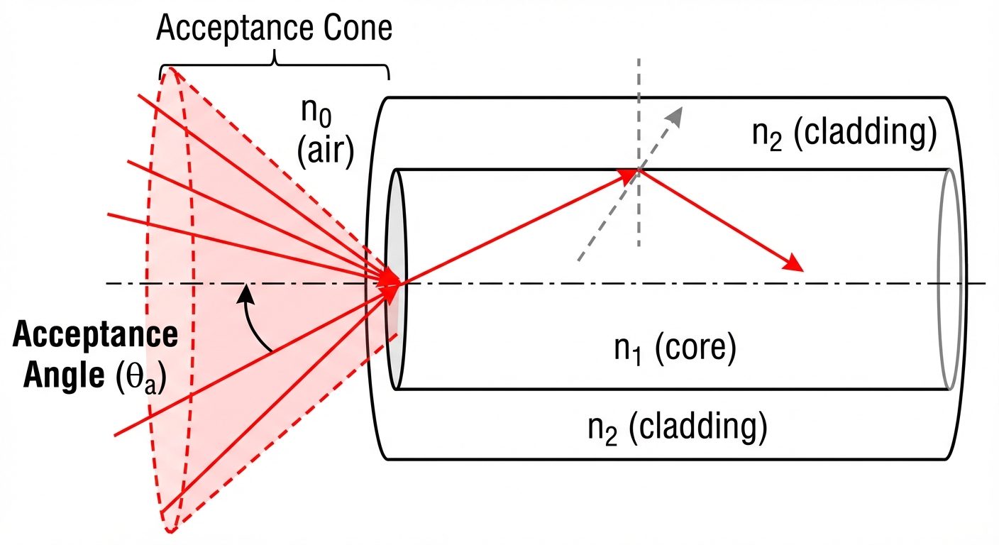
4. Acceptance Angle () and Numerical Aperture (NA)
For light to propagate through the fiber via TIR, it must enter the fiber core within a specific cone of angles.
Acceptance Angle ()
The maximum angle to the fiber axis at which light may enter the fiber in order to be propagated is called the acceptance angle.
- If the launch angle , the internal ray will hit the cladding at an angle less than the critical angle and will refract out (loss).
- If the launch angle , TIR occurs.
Derivation:
Applying Snell's law at the air-core interface (launch point):
Substituting :
Assuming the surrounding medium is air ():
Numerical Aperture (NA)
The Numerical Aperture is a measure of the light-gathering ability of the fiber. It is defined as the sine of the acceptance angle.
Relative Refractive Index Difference ()
The fractional difference between the refractive indices of the core and cladding.
Since , is usually very small (typically 0.01 or 1%).
Relation between NA and :
5. The V-Number (Normalized Frequency)
The V-number is a dimensionless parameter that determines the number of modes (paths) a fiber can support.
Formula:
Where:
- = Radius of the fiber core
- = Wavelength of the light source
- = Numerical Aperture
Significance:
- Single Mode Operation: If , the fiber supports only one mode (Single Mode Fiber - SMF).
- Multimode Operation: If , the fiber supports multiple modes (Multimode Fiber - MMF).
- Number of Modes ():
- For Step Index Fiber:
- For Graded Index Fiber:
6. Classification of Optical Fibers
Fibers are classified based on the refractive index profile and the number of modes.
A. Based on Refractive Index Profile
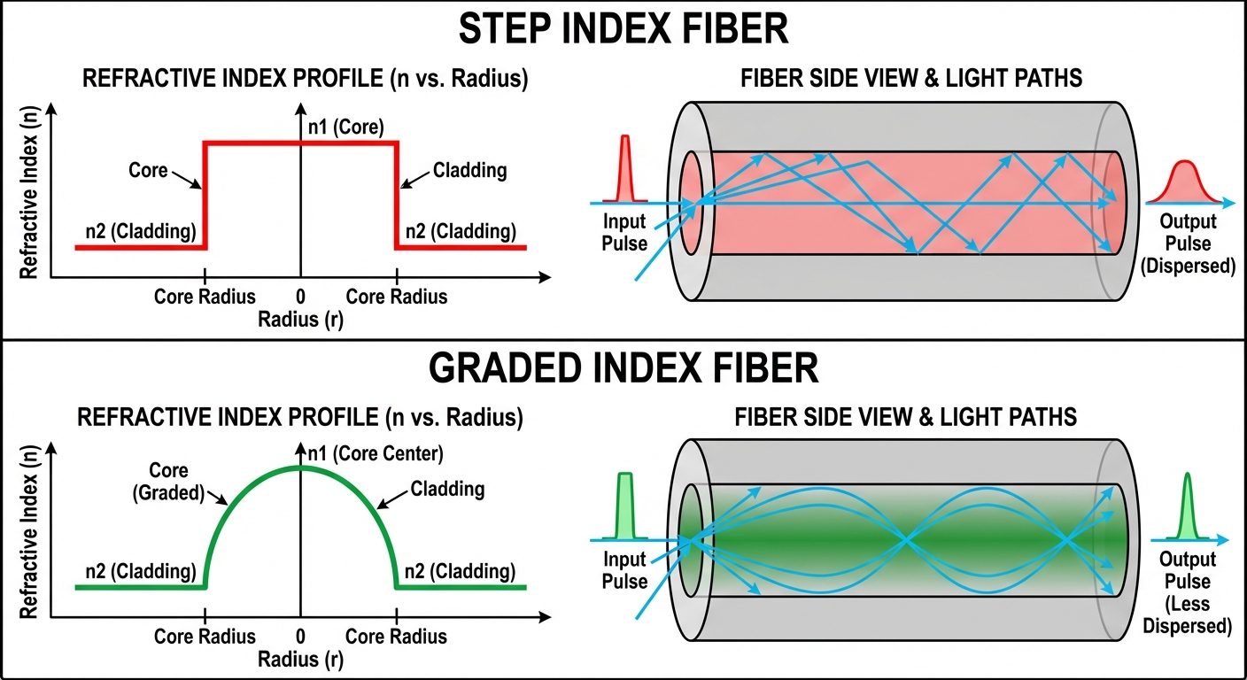
1. Step Index Fiber
- Profile: The refractive index is constant throughout the core () and undergoes an abrupt change (step) at the cladding interface ().
- Path: Light travels in zig-zag paths.
- Disadvantage: Suffers from Intermodal Dispersion (rays taking different paths arrive at different times), limiting bandwidth.
2. Graded Index (GRIN) Fiber
- Profile: The refractive index of the core is non-uniform. It is maximum at the axis and decreases parabolically towards the cladding.
- Path: Light travels in helical/sinusoidal paths. Rays traveling near the edge travel faster (lower refractive index) than rays at the center, compensating for the longer distance.
- Advantage: Significantly reduces Intermodal Dispersion.
B. Based on Modes
| Feature | Single Mode Fiber (SMF) | Multimode Fiber (MMF) |
|---|---|---|
| Core Diameter | Very small () | Larger () |
| Light Source | Laser | LED |
| V-Number | ||
| Distance | Long-distance comms | Short-distance (LANs) |
| Dispersion | Almost zero intermodal dispersion | High dispersion |
7. Losses in Optical Fibers (Attenuation)
Attenuation represents the reduction in signal strength as light travels down the fiber. It is measured in decibels per kilometer (dB/km).
Formula:
Where is length in km, is input power, and is output power.
Major Sources of Loss
1. Absorption Losses
- Intrinsic Absorption: Caused by the interaction of light with the glass material itself (infrared absorption by silica).
- Extrinsic Absorption: Caused by impurities like transition metal ions (Fe, Cr, Ni) and Hydroxyl ions () from water.
2. Scattering Losses (Rayleigh Scattering)
- Caused by microscopic variations in the material density and composition formed during the manufacturing process.
- Light hits these fluctuations and scatters in all directions.
- Loss is inversely proportional to the fourth power of wavelength ().
3. Bending Losses
- Macrobending: Occurs when the fiber is bent with a radius visible to the human eye. The incidence angle at the bend becomes less than the critical angle, causing light to leak out.
- Microbending: Caused by microscopic imperfections in the fiber geometry or pressure from the cabling process, causing mode coupling and leakage.
4. Dispersion (Signal Distortion)
While not strictly a power "loss," dispersion spreads the optical pulse over time, degrading the signal quality.
- Intermodal Dispersion: Difference in travel times between different modes (in MMF).
- Intramodal (Chromatic) Dispersion: Different wavelengths travel at different speeds (since refractive index depends on wavelength).