Unit 5 - Notes
Unit 5: Isometric Views
1. Introduction
Isometric projection is a method of visual representation in three dimensions. It is a form of pictorial drawing where all three principal axes of the object are inclined equally to the plane of projection. The term "Isometric" comes from Greek, meaning "equal measure."
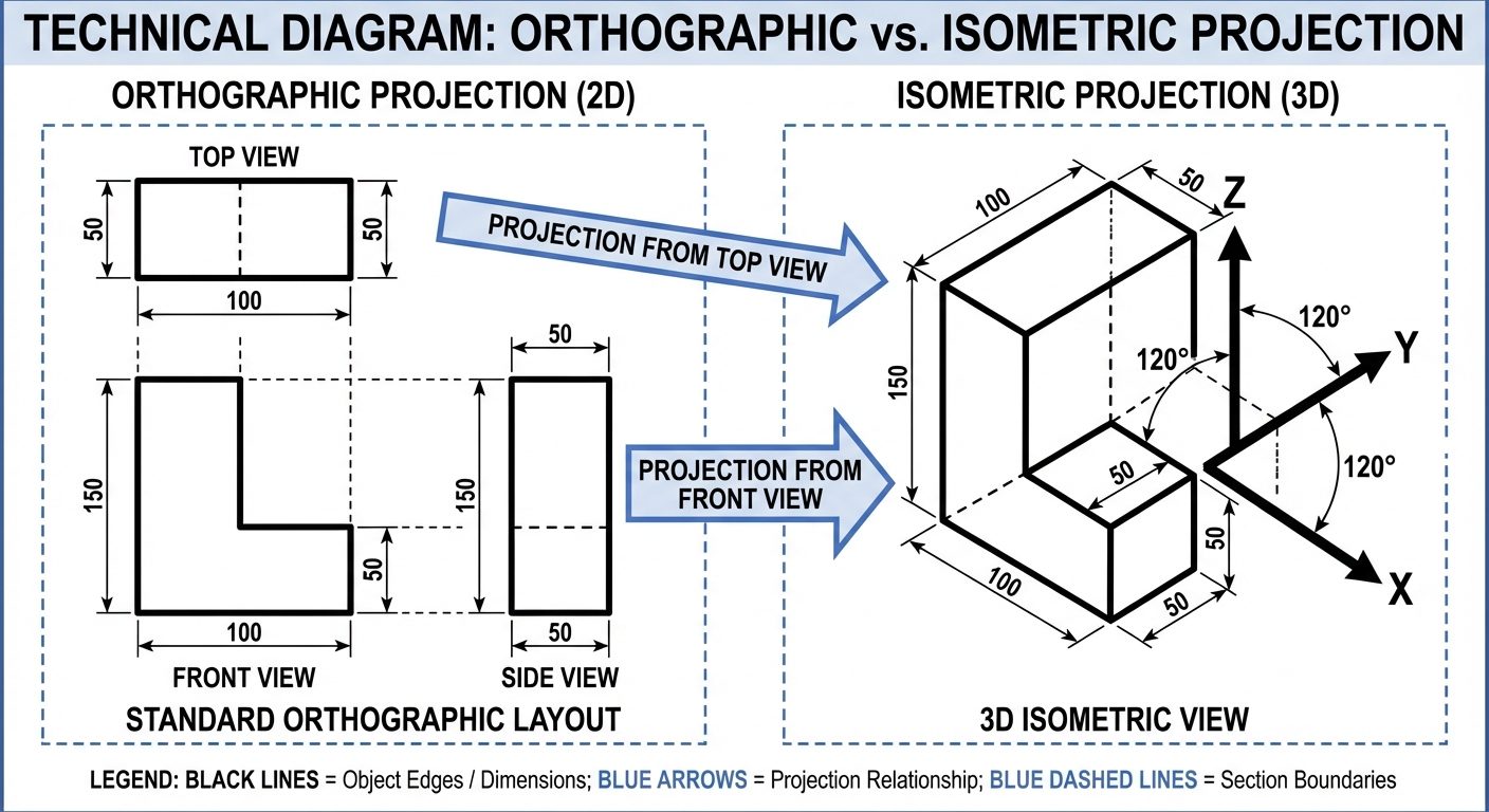
In engineering drawing, isometric views allow the observer to see the top, front, and side views of an object simultaneously in a single drawing.
Key Characteristics
- Three Dimensional: Shows length, width, and height.
- Equal Foreshortening: All three axes are foreshortened equally (approx. 82% of true length in projection).
- Angle of Inclination: The three principal axes meet at a point and are 120° apart from each other.
2. Terminology
Understanding the specific vocabulary is essential for constructing isometric views.
Isometric Axes
The three lines meeting at a point and making an angle of 120° with each other are called Isometric Axes.
- One axis is usually vertical (Height).
- The other two axes (Length and Width) are inclined at 30° to the horizontal base line.
Isometric Lines
Lines drawn parallel to the isometric axes are called Isometric Lines.
- Rule: Measurements can only be made directly on isometric lines.
Non-Isometric Lines
Lines that are not parallel to the isometric axes are called Non-Isometric Lines.
- Rule: These lines generally represent inclined edges. Their true lengths cannot be measured directly. They must be drawn by locating their endpoints using isometric coordinates (Box Method).
Isometric Planes
The planes representing the faces of the isometric cube are called Isometric Planes.
- Top Plane (Iso-Top): Defined by the two 30° axes.
- Left Plane (Iso-Left): Defined by the vertical axis and left 30° axis.
- Right Plane (Iso-Right): Defined by the vertical axis and right 30° axis.
3. Isometric Scale
In a true Isometric Projection, the object is tilted such that the edges are foreshortened. However, in an Isometric View (or Drawing), engineers often draw using the true scale for convenience.
Difference between Projection and View
- Isometric View/Drawing: Drawn using True Scale (1:1). The object appears larger than it would in reality if viewed from that angle.
- Isometric Projection: Drawn using Isometric Scale. The object appears at its optically correct size (foreshortened).
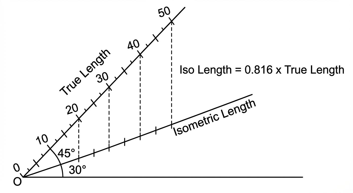
Constructing the Isometric Scale
The relation between True Length and Isometric Length is derived mathematically:
Construction Steps:
- Draw a horizontal line.
- Draw a line at 45° (representing True Scale).
- Draw a line at 30° (representing Isometric Scale).
- Mark divisions on the 45° line and project them vertically down to the 30° line.
4. Isometric Views of Solids
The most common technique for drawing isometric views is the Box Method (or Enclosing Box Method).
Isometric Views of Prisms (Cube, Rectangular, Triangular, Hexagonal)
Method:
- Imagine the prism is enclosed in a rectangular box with dimensions equal to the overall length, width, and height of the prism.
- Draw the isometric box (axes at 30°, 30°, and 90°).
- Mark the points of the base shape (e.g., hexagon corners) on the faces of the box.
- Transfer these points to the top face.
- Join the points with visible (solid) and hidden (dashed) lines as per convention.
- Note: Vertical edges of prisms remain vertical.
Isometric Views of Pyramids
Pyramids have a base and an apex.
Method:
- Draw the isometric view of the base (using the Box Method).
- Locate the Center of the base by drawing diagonals or bisectors.
- From the center, draw a vertical line representing the Axis Height.
- Mark the Apex at the top of the axis.
- Join the apex to all corners of the base.
One Object on Another (Composite Solids)
Common in engineering components (e.g., a cylinder on a cube).
Method:
- Draw the bottom solid first completely.
- Locate the center of the top face of the bottom solid.
- Use this center point as the reference to start drawing the base of the top solid.
- Centering Rule: Ensure the axes of both solids are collinear (aligned).
- Erase internal lines that are hidden by the superimposition.
5. Dimensioning in Isometric Views
Dimensioning isometric drawings requires specific alignment rules to maintain the 3D illusion.
- Aligned System: Dimensions are always placed using the Aligned system.
- Extension Lines: Must be drawn parallel to the isometric axes (extension of the object lines).
- Dimension Lines: Must be parallel to the object line being measured.
- Text/Arrowheads: Dimension text should be written such that it appears to lie on the isometric plane.
Common Mistake: Do not draw extension lines horizontally or vertically (orthographically) unless the object line is vertical.
6. AutoCAD Commands for 3D Modeling
While the previous sections cover manual drafting theory, modern engineering relies on AutoCAD 3D.
Transitioning to 3D Workspace
- Switch workspace to "3D Modeling".
- View Control: Change view from "Top" to "SE Isometric" or "SW Isometric".
- Visual Style: Change from "2D Wireframe" to "Conceptual" or "Realistic".
3P UCS Rotation (3-Point User Coordinate System)
The UCS defines the drawing plane. In 3D, you often need to draw on a slanted face.
- Command:
UCS>3Point(or type3P). - Process:
- Specify new Origin (0,0,0).
- Specify a point on the positive X-axis.
- Specify a point on the positive Y-axis.
- Utility: Allows drawing standard 2D shapes on any arbitrary face of a 3D object.
Standard Shapes (Primitives)
AutoCAD provides pre-built 3D solids:
- Box: Creates a cuboid. Requires corner point, length, width, and height.
- Cylinder: Requires center point, radius, and height.
- Cone: Requires center point, base radius, and height.
- Sphere: Requires center point and radius.
- Wedge: A standard wedge shape.
- Torus: A donut shape (tube radius and major radius).
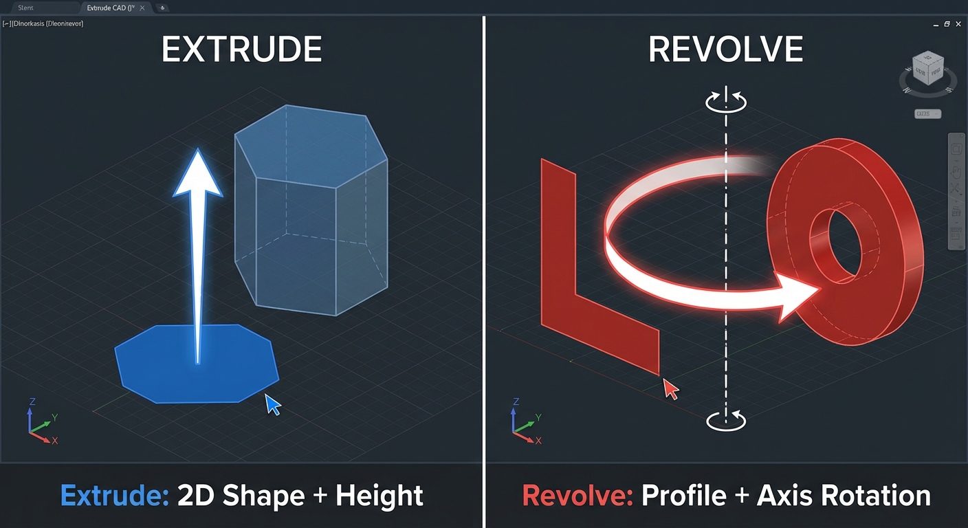
Extrude (EXTRUDE)
Converts a 2D closed profile into a 3D solid.
- Requirement: The 2D object must be a
REGIONor a closedPOLYLINE. - Process: Select object > Enter Height of extrusion.
- Example: Drawing a rectangle and extruding it creates a box.
Revolve (REVOLVE)
Creates a solid by sweeping a 2D profile around an axis.
- Requirement: A closed profile and an axis line.
- Process: Select profile > Select Axis > Enter Angle of Revolution (usually 360°).
- Usage: Used for cylindrical/symmetrical objects (e.g., pulleys, shafts, bottles).
Presspull (PRESSPULL)
A versatile modeling tool that simplifies Extrude.
- Function: Automatically detects bounded areas (closed regions).
- Process: Hover inside a closed area > Click > Drag mouse to give height.
- Difference from Extrude: Presspull can subtract material (make a hole) if dragged into the solid, and it does not require the profile to be joined as a polyline first.
7. Hands-on Practice: Creating a 3D Bracket
To master Unit 5, follow this workflow for a typical machine bracket:
Step 1: Setup
- Command:
UNITS(Set to Millimeters). - Command:
VS(Visual Styles) -> Conceptual. - View: SE Isometric.
Step 2: Create Base
- Draw the base profile using
PLINE(Polyline). - Command:
EXTRUDE-> Select profile -> Height: 20mm.
Step 3: Create Vertical Support
- Move UCS to the top face of the base (
UCS->Face). - Draw the vertical profile.
- Command:
PRESSPULL-> Pull upwards to 50mm.
Step 4: Add Holes
- Draw circles on the respective faces.
- Command:
PRESSPULL-> Select inside the circle -> Drag downwards through the material to cut a hole.
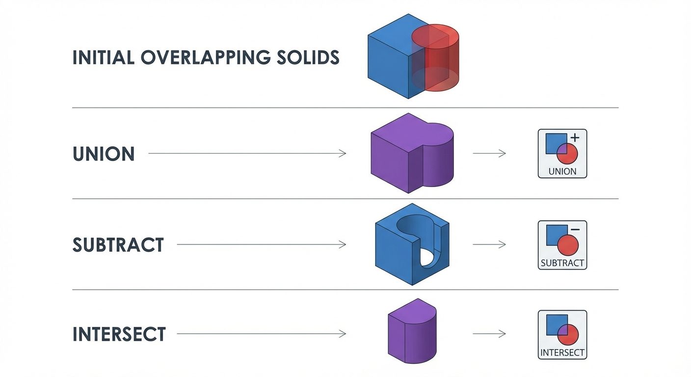
Step 5: Union
- If the object consists of separate parts, use
UNIONcommand to merge them into a single solid entity.