Unit 4 - Notes
Unit 4: Sectional Views
1. Introduction to Sectional Views
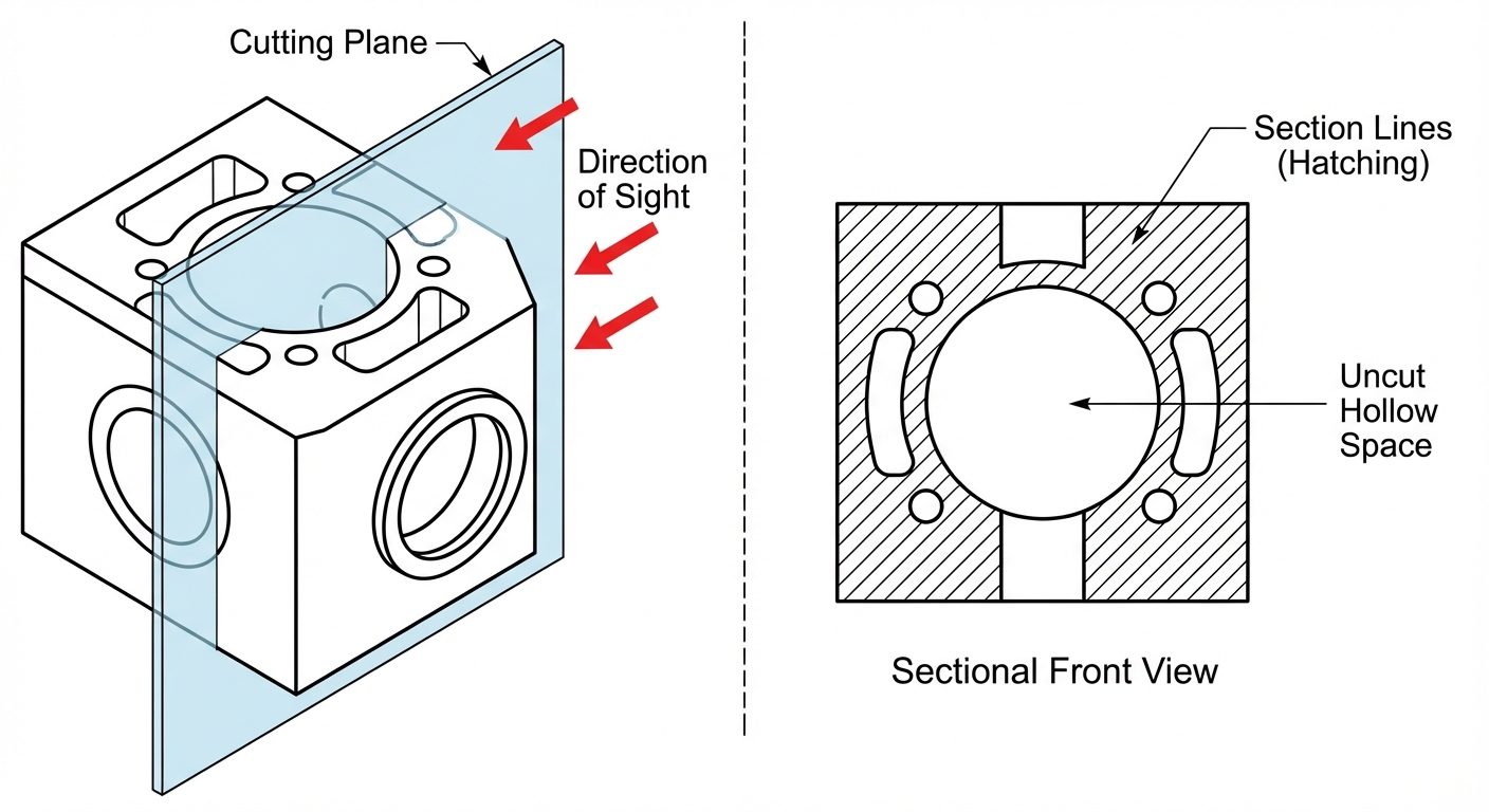
In engineering drawing, internal details of complex objects (such as engine blocks, valves, or brackets) are often difficult to visualize using only hidden lines (dashed lines). Hidden lines can become cluttered and confusing. To solve this, we use Sectional Views.
- Definition: A sectional view is obtained by imagining that a portion of the object has been cut away by a "cutting plane" to reveal internal construction.
- Purpose:
- To clarify internal features (holes, slots, cavities).
- To reduce the number of confusing hidden lines.
- To facilitate dimensioning of internal features.
2. Principles of Sectioning
The Cutting Plane
The imaginary surface that cuts through the object is called the Cutting Plane.
- Cutting Plane Line: Representation of the cutting plane in the adjacent view. It is a thick line with a pattern of one long dash and two short dashes.
- Arrows: Placed at the ends of the cutting plane line to indicate the direction of sight.
Section Lines (Hatching)
The surface created by cutting the object is represented by Section Lines (also known as Hatching).
- Standard Pattern: Thin, continuous lines drawn at a 45° angle to the main outline.
- Spacing: Uniform spacing (usually 2mm to 3mm), depending on the size of the drawing.
- Material Indication: Different hatch patterns can represent different materials (e.g., cast iron, steel, concrete), though simple diagonal lines are the general standard for "metal."
Important Rules
- Hidden Lines: Generally, hidden lines are omitted in sectional views unless necessary for clarity.
- Ribs and Webs: If a cutting plane passes longitudinally (lengthwise) through a stiffening rib, web, or spoke, that feature is NOT hatched. This distinguishes a thin rib from a solid mass.
- Fasteners: Standard parts like bolts, nuts, screws, rivets, and shafts are not hatched even if the cutting plane passes through them.
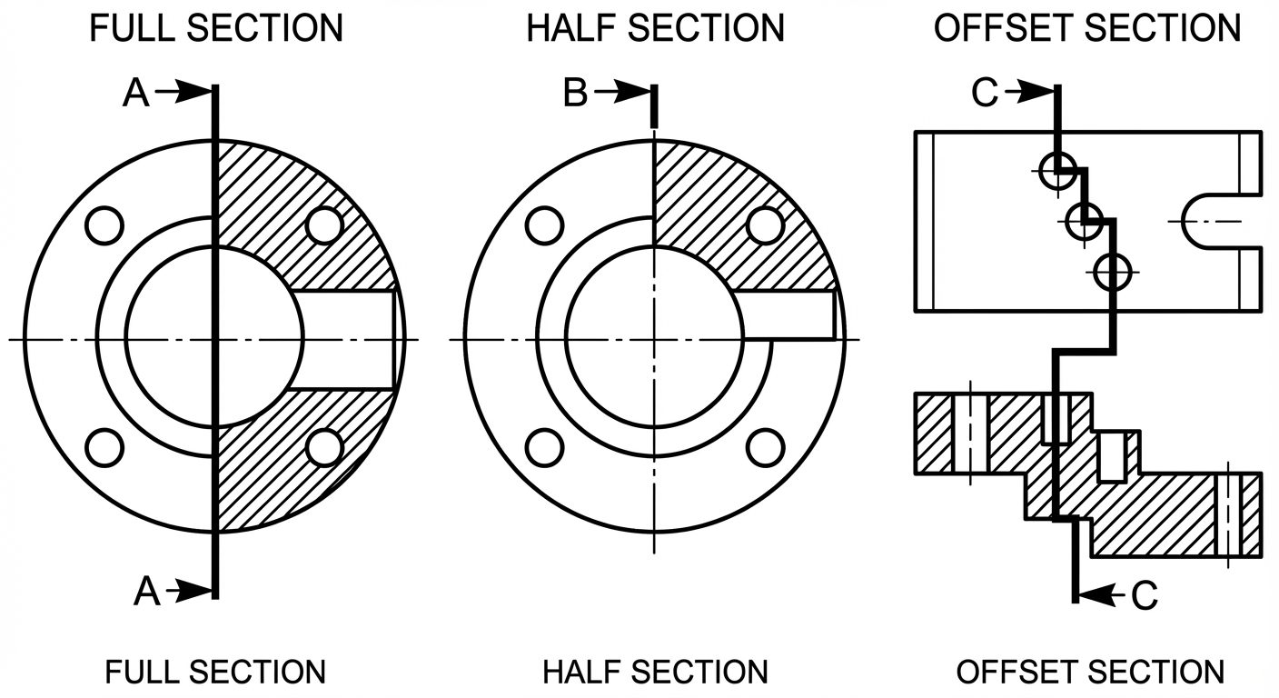
3. Types of Sectional Views
A. Full Section
- The cutting plane passes entirely through the object in a straight line.
- The view replaces the standard exterior view.
- Used when the internal detail is complex throughout the entire length of the part.
B. Half Section
- The cutting plane passes only halfway through the object (removing one-quarter of the object).
- Usage: Ideally used for symmetrical objects (cylinders, pulleys).
- Result: One half of the view shows the exterior appearance; the other half shows the interior section.
- Separation: The sectioned half is separated from the un-sectioned half by a center line (not a solid line).
C. Offset Section
- The cutting plane is "stepped" or bent at 90° angles to pass through features that do not lie in a straight line.
- Allows the capture of multiple staggered holes or features in a single view.
- In the sectional view, no line is drawn indicating the change in direction of the cutting plane.
4. Projection Systems in Sectioning
The projection rules for sectional views follow standard orthographic projection principles (First Angle vs. Third Angle). The appearance of the section itself does not change, but its position on the drawing sheet does.
First Angle Projection
- Principle: Object is placed in the First Quadrant (Object between Observer and Plane).
- Position: The Sectional Front View is drawn above the Top View. A Sectional Side View is drawn on the side opposite to the viewing direction.
Third Angle Projection
- Principle: Object is placed in the Third Quadrant (Plane between Observer and Object).
- Position: The Sectional Front View is drawn below the Top View. The Sectional Side View is drawn adjacent to the Front View on the same side as the viewing direction.
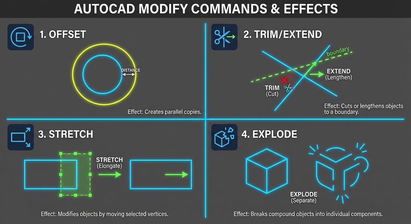
5. AutoCAD Commands: Modify Tools
To create sectional views efficiently, one must master specific Modify commands to manipulate geometry.
STRETCH (Command: S)
- Function: Stretches objects crossed by a selection window or moves objects completely inside the window.
- Usage: Useful for lengthening a shaft or moving a hole location without redrawing the whole part.
- Note: You must use a "Crossing Selection" (Green window, right-to-left) to select the vertices to stretch.
EXPLODE (Command: X)
- Function: Breaks a compound object (like a Block, Polyline, or Hatch) into its component objects.
- Usage: Converting a rectangle into four separate lines to trim specific segments.
OFFSET (Command: O)
- Function: Creates concentric circles, parallel lines, or parallel curves.
- Usage: The most used command for drawing walls, thickness of pipes, or spacing between features.
EXTEND (Command: EX)
- Function: Extends a line or arc to meet another object (boundary edge).
- Usage: Closing gaps between lines to ensure a closed boundary for hatching.
JOIN (Command: J)
- Function: Combines similar objects (like collinear lines or arcs) into a single object.
- Usage: Reconnecting lines after a
BREAKcommand or converting segments into a polyline.
REGION (Command: REG)
- Function: Converts objects that enclose an area into a 2D region object (planar surface).
- Usage: Essential for calculating properties (Area, Centroid) or performing Boolean operations (Union, Subtract).
BREAK (Command: BR)
- Function: Creates a gap in an object or breaks it into two points.
- Usage: Removing a section of a line where a feature intersects it.
6. AutoCAD Commands: Hatching
HATCH (Command: H or BHATCH)
The HATCH command fills an enclosed area with a pattern.
- Ribbon Tab: Opens the "Hatch Creation" tab.
- Pick Points: The easiest method. Click inside an enclosed area to hatch it. AutoCAD calculates the boundary automatically.
- Select Objects: Select specific closed polylines or circles to hatch.
- Properties to Adjust:
- Pattern:
ANSI31(Standard iron/steel),ANSI32(Steel),AR-CONC(Concrete). - Angle: Default is 0 (which appears as 45° for ANSI31). Can be rotated.
- Scale: Increases or decreases the density of the pattern. If hatch looks solid, increase scale; if invisible, decrease scale.
- Pattern:
HATCH-EDIT (Command: HE)
- Function: Modifies an existing hatch pattern.
- Usage: Double-click an existing hatch to open the editor. Used to change the angle, scale, or pattern type without deleting and redrawing.
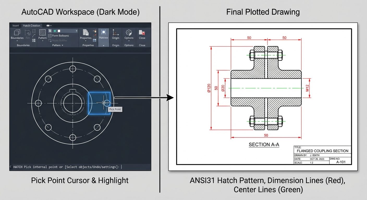
7. Hands-on Practice: Creating a Sectional View
Step-by-Step Procedure on 2D Drawings
Problem: Draw the Sectional Front View and Top View of a hollow Cast Iron Cylinder.
-
Setup:
- Set Units (
UN) to Millimeters. - Set Limits and Zoom All (
Z>A). - Create Layers:
Outline(White, Continuous),Centerline(Red, Center),Hatch(Blue, Continuous),CuttingPlane(Magenta, Phantom).
- Set Units (
-
Draw Top View (Standard):
- Use
CIRCLEto draw outer and inner diameters. - Draw center lines.
- Use
-
Project Front View:
- Use
XLINE(Construction Line) orRAYto project width from the top view circles. - Draw the height of the cylinder using
LINE. - Use
OFFSETto create the floor and wall thickness.
- Use
-
Define Cutting Plane:
- In the Top View, draw the cutting plane line passing through the center. Add arrows pointing Up (for First Angle) or the direction of the front view.
-
Create Sectional View:
- In the Front View, identify the areas cut by the plane (the solid walls).
- Trim (
TR) any lines that shouldn't be visible. - Ensure the boundary of the cut area is completely closed.
-
Apply Hatching:
- Switch to
Hatchlayer. - Command:
H. - Pattern:
ANSI31. - Scale: Set to
1.0(adjust until lines are distinct). - Click inside the solid wall areas. Do not hatch the hollow center.
- Switch to
-
Finalize:
- Add Dimensions (
DIM). - Add Text (
MTEXT) labeling "SECTION A-A".
- Add Dimensions (