Unit 6 - Notes
Unit 6: Development of Surfaces
1. Introduction to Development of Surfaces
Definition:
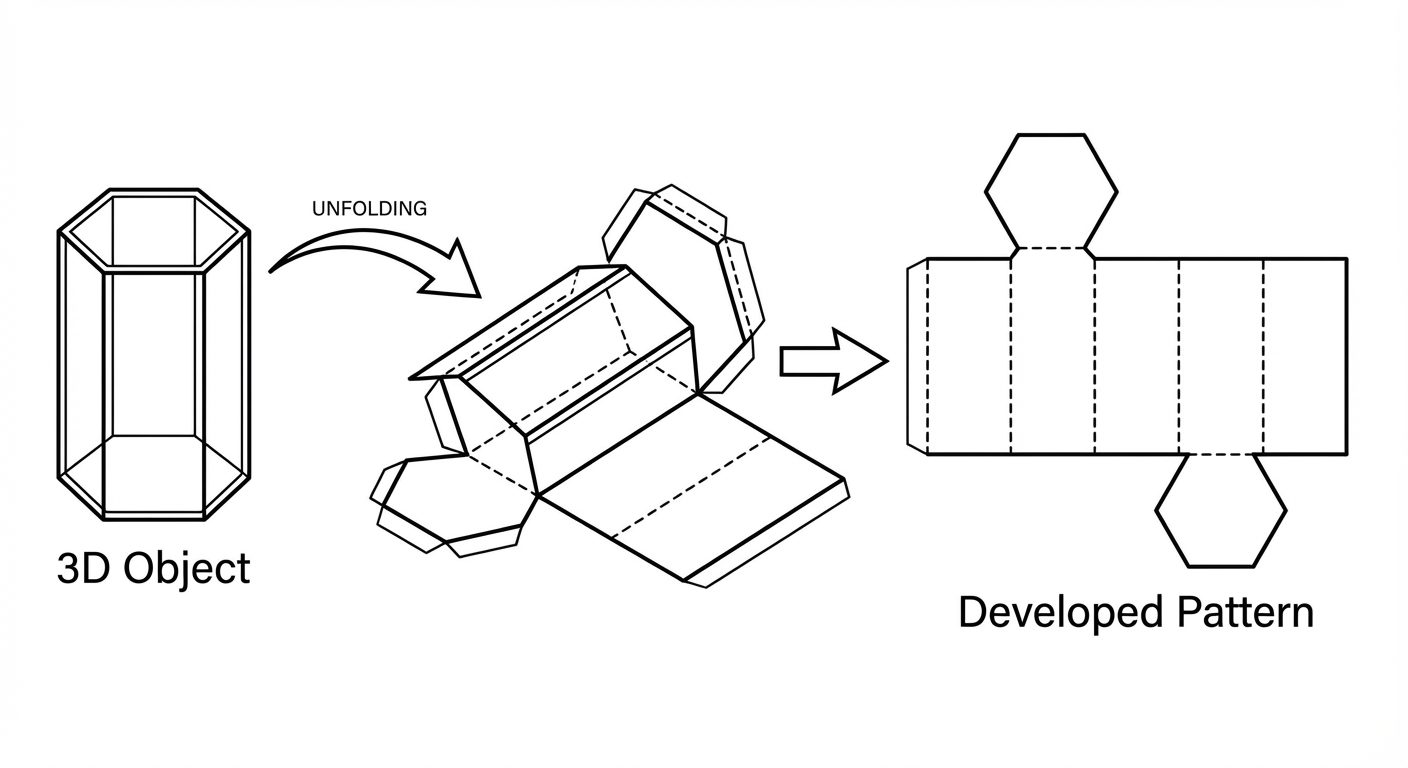
The development of a surface of an object is the unfolding or unrolling of all its surfaces onto a single plane. If a hollow solid is cut open along an edge and rolled out flat on a plane, the resulting 2D figure is called the Development of the Surface or a Pattern.
Key Concepts:
- Principle of Development: Every line on the development must represent the True Length (TL) of the corresponding line on the surface of the object.
- Stretch-out Line: The full length of the developed surface (e.g., the circumference of a cylinder or perimeter of a prism).
- Applications: Essential in sheet metal industries for making ducts, funnels, chimney flues, boiler parts, packaging boxes, and automobile body parts.
2. Methods of Development
Different solids require different geometric techniques to be unfolded accurately.
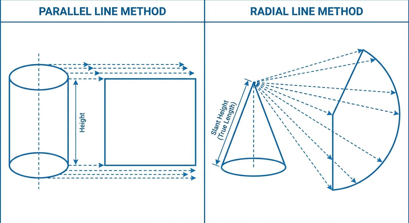
A. Parallel Line Development
- Used for: Prisms and Cylinders.
- Concept: Since the edges of prisms and elements of cylinders are parallel to each other, they are developed using a rectangle where the length equals the perimeter/circumference of the base, and the height equals the height of the solid.
B. Radial Line Development
- Used for: Pyramids and Cones.
- Concept: Since the edges/elements slant towards a common apex, the development is drawn as a sector of a circle. The radius of this sector is the True Length of the slant edge.
C. Triangulation Development
- Used for: Irregular polyhedrons and Transition pieces (e.g., connecting a square pipe to a circular pipe).
- Concept: The surface is divided into a series of triangular faces. The true sizes of these triangles are found and arranged sequentially.
D. Approximate Development
- Used for: Double curved surfaces like Spheres and Paraboloids.
- Concept: These surfaces cannot be developed exactly. They are approximated using zones (Polyconic method) or gores (Lune method).
3. Surface Development of Solids
A. Development of Regular Prisms
- Procedure:
- Draw the Top View (TV) and Front View (FV).
- Draw a "Stretch-out line" horizontally from the base of the FV.
- Mark off distances equal to the side of the base () along this line (, where is the number of sides).
- Erect vertical lines from these points representing the edges.
- The resulting rectangle represents the lateral surface.
B. Development of Truncated Prisms
A truncated prism is cut by a plane inclined to the base.
- Procedure:
- Draw TV and FV. Draw the cutting plane in the FV.
- Draw the lateral development as if the prism were complete.
- Project the intersection points of the cutting plane and the prism edges horizontally onto the corresponding vertical lines in the development.
- Join these points with straight lines.
- Darken the remaining lower portion to show the developed surface of the truncated solid.
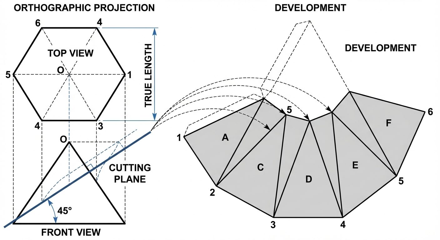
C. Development of Regular Pyramids
- Critical Rule: You must use the True Length (TL) of the slant edge. If the slant edge in the Front View is not parallel to the XY line in the Top View, the length shown in FV is apparent, not true. You must rotate the edge in TV to make it parallel to XY, then project to FV to find TL.
- Procedure:
- Find True Length () of the slant edge.
- Draw an arc with radius .
- Step off chord lengths equal to the base side () along the arc.
- Join these points to the center (Apex ).
D. Development of Truncated Pyramids
- Procedure:
- Draw the development of the full pyramid using the Radial Line method.
- Locate the cutting plane on the FV.
- Transfer the cut points from the slant edges in the FV to the True Length line (usually the outer edge in FV). Note: You cannot project directly to the development if the edge isn't TL.
- Transfer these distances from the TL line to the corresponding radial lines in the development using a compass.
- Join the points to form the pattern.
4. AutoCAD Commands for 3D Modeling
Moving from 2D development to 3D modeling requires specific solid modeling commands.
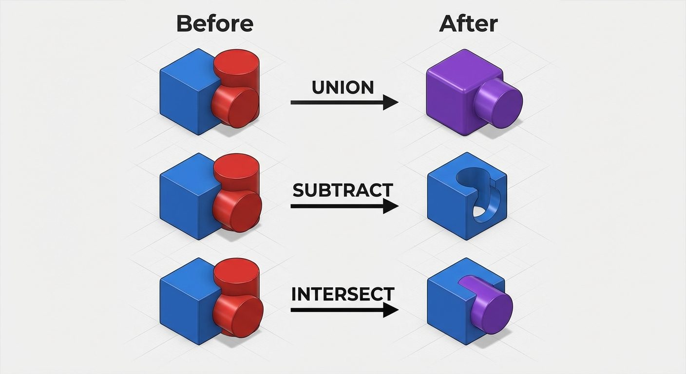
Boolean Operations
These commands allow the creation of complex solids by combining simpler primitives (Box, Cylinder, Wedge, etc.).
- UNION (
UNION):- Combines two or more 3D solids or 2D regions into a single composite object.
- Usage: Select the command Select objects to join Enter.
- SUBTRACT (
SUBTRACT):- Removes the volume of one set of solids from another.
- Usage: Select the command Select the object to keep (Base) Enter Select the object to remove (Cutter) Enter.
- Note: The order of selection is critical.
- INTERSECT:
- Creates a solid from the overlapping volume of two or more solids.
Navigation and Visualization
-
3D ORBIT (
3DORBITor Shift + Middle Mouse Wheel):- Allows you to rotate the view in 3D space freely to inspect the model from any angle.
- The cursor changes to a sphere with circling arrows.
-
Visual Styles (
VS):
Controls the display of edges and shading.- 2D Wireframe: Displays boundaries using lines and curves. Fastest for processing.
- Conceptual: Smoothes polygon edges and applies "Gooch" shading (cool to warm transition) for easy geometry visualization.
- Realistic: Applies materials and textures to the object.
- Hidden: Wireframe display but lines behind the object are removed.
5. Hands-on Practice: 3D Drawings
Exercise: Modeling a Truncated Square Prism
Objective: Create a square prism ( base, $100$ height) cut by a plane at .
Step-by-Step Procedure:
-
Workspace Setup:
- Switch to "3D Modeling" workspace.
- Set View to "SE Isometric".
- Set Visual Style to "2D Wireframe" initially.
-
Create the Base (Prism):
- Command:
BOX(orRECTANGthenEXTRUDE). - Specify first corner:
0,0,0. - Specify other corner (Length/Width):
@50,50. - Specify Height:
100. - Result: A solid block is created.
- Command:
-
Create the Cutting Object (The "Knife"):
- To slice the object, we often create a "wedge" or a second large box to subtract.
- Change UCS (User Coordinate System) to the Front face: Command
UCSFaceSelect front face. - Draw a
PLINE(Polyline) representing the shape to be removed (a triangle defining the 45-degree cut). EXTRUDEthis triangle through the prism.
-
Apply Boolean Operation:
- Command:
SUBTRACT. - Select the main Prism (Enter).
- Select the triangular extrusion (Enter).
- Result: The prism is now truncated.
- Command:
-
Final Visualization:
- Command:
VSSelectConceptual. - Command:
3DORBITRotate to inspect the cut surface.
- Command:
Tips for Success:
- Always ensure your OSNAP (Object Snap) is ON to grab endpoints accurately.
- Use Dynamic UCS (F6) to draw directly on planar faces of existing solids.
- If the subtraction fails, ensure the two solids physically intersect.