Unit 3 - Notes
Unit 3: Orthographic Projections
1. Introduction and Principles
1.1 Definition
Orthographic projection is a method of representing three-dimensional objects on a two-dimensional surface using parallel lines of projection (projectors) that are perpendicular to the plane of projection. The term comes from the Greek words orthos (straight) and graphē (drawing). It is the universal language of technical drawing and engineering.
1.2 Basic Principles
The primary objective is to describe the shape of an object completely and exactly using two or more views.
- The Projectors: Lines of sight from the observer's eye to the object. In orthographic projection, these are parallel to each other.
- The Plane of Projection: The flat surface on which the image is captured (e.g., the paper or screen).
- The Object: The 3D geometry being drawn.
- Perpendicularity: The projectors strike the plane of projection at a 90° angle.
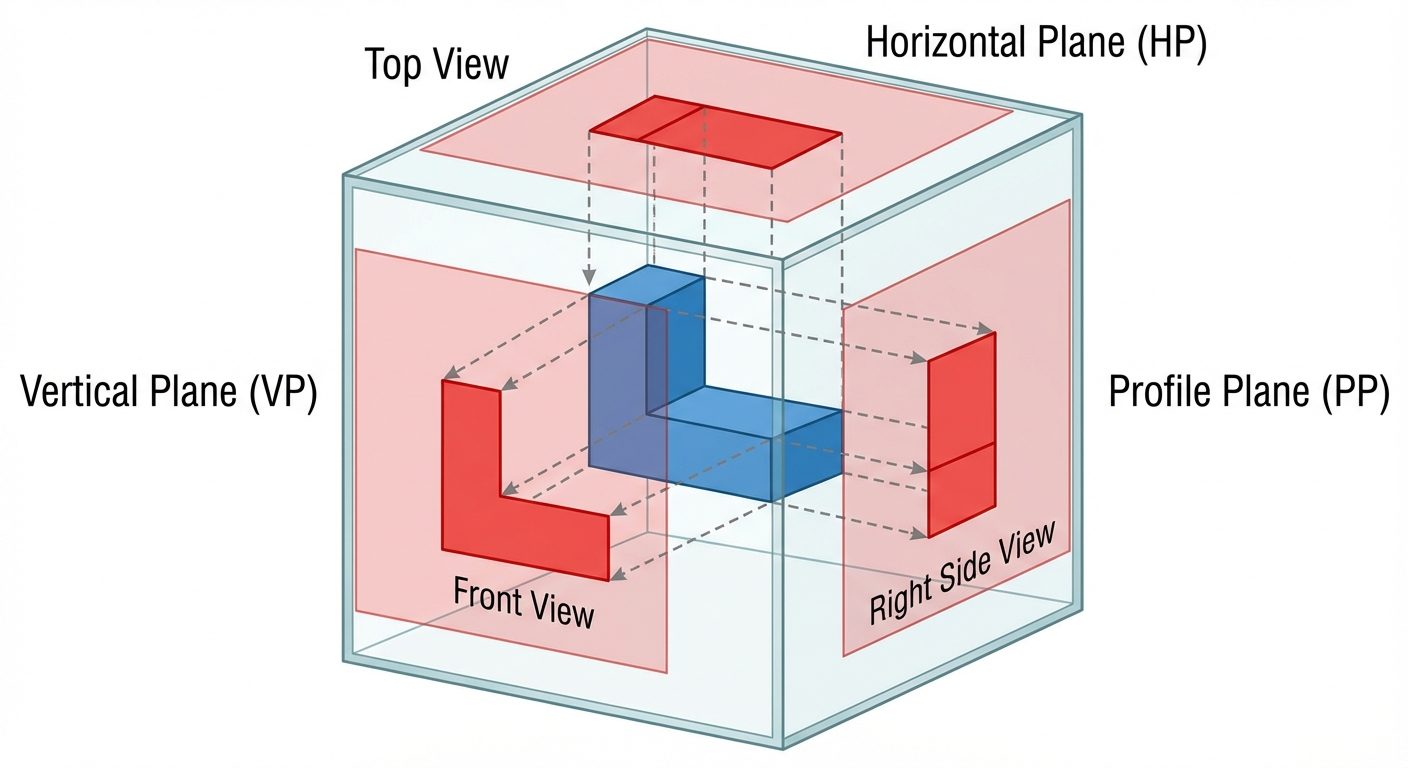
1.3 Principal Planes and Views
To define an object fully, we generally project it onto three mutually perpendicular planes:
- Vertical Plane (VP): Generates the Front View (Elevation). Shows length and height.
- Horizontal Plane (HP): Generates the Top View (Plan). Shows length and width (depth).
- Profile Plane (PP): Generates the Side View (Profile View). Shows width and height.
2. Projection Systems: First Angle vs. Third Angle
The intersection of the Vertical Plane and Horizontal Plane creates four quadrants. The position of the object relative to these planes determines the projection system used.
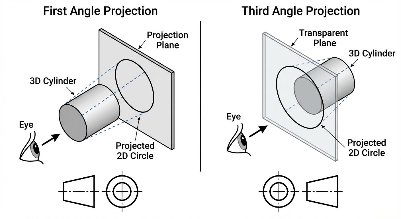
2.1 First Angle Projection
Used primarily in Europe and India (ISO Standard).
- Position: The object is placed in the First Quadrant (above HP, in front of VP).
- Logic: Observer → Object → Plane.
- Concept: The plane of projection is assumed to be opaque (like a wall behind the object).
- View Arrangement:
- Top View is drawn BELOW the Front View.
- Right Side View is drawn to the LEFT of the Front View.
- Left Side View is drawn to the RIGHT of the Front View.
2.2 Third Angle Projection
Used primarily in the USA and Canada (ANSI Standard).
- Position: The object is placed in the Third Quadrant (below HP, behind VP).
- Logic: Observer → Plane → Object.
- Concept: The plane of projection is assumed to be transparent (like a glass pane between the observer and object).
- View Arrangement:
- Top View is drawn ABOVE the Front View.
- Right Side View is drawn to the RIGHT of the Front View.
- Left Side View is drawn to the LEFT of the Front View.
2.3 Comparison Summary
| Feature | First Angle Projection | Third Angle Projection |
|---|---|---|
| Object Position | 1st Quadrant (Above HP, In front VP) | 3rd Quadrant (Below HP, Behind VP) |
| Projection Plane | Non-transparent (Opaque) | Transparent (Glass) |
| Sequence | Observer - Object - Plane | Observer - Plane - Object |
| Top View Location | Below Front View | Above Front View |
| Symbol | Frustum of cone: Small circle on right | Frustum of cone: Small circle on left |
3. Practice: Converting Isometric to Orthographic
When converting a 3D isometric view to orthographic views, follow this workflow:
- Analyze the Object: Identify overall Length (L), Width (W), and Height (H).
- Determine Views:
- Front View: Usually view perpendicular to the longest dimension or the view showing the most detail.
- Top View: Looking strictly from above.
- Side View: Looking from the left or right.
- Layout (Sheet Planning):
- Draw the Reference Line (XY line).
- Leave equal spacing between views.
- Projection:
- Draw the Front View first.
- Project vertical lines down (or up) for the Top View (Length remains constant).
- Project horizontal lines to the side for the Side View (Height remains constant).
- Use a 45° miter line to transfer depth dimensions between Top and Side views.
4. AutoCAD Commands
Efficient drafting relies on mastering Modify commands and Property management.
4.1 Linetype and Properties
Technical drawings utilize specific line types to convey meaning (e.g., hidden features, center points).
- Properties Palette (
CTRL+1): A centralized panel to view and modify layer, color, linetype, and line weight of selected objects. LINETYPECommand: Loads different line styles.- Continuous: Visible outlines (Thick).
- Hidden (Dashed): Invisible edges (Medium).
- Center (Long-short-long): Axis of symmetry (Thin).
LTSCALE: Adjusts the global scale factor of linetypes (controls the spacing of dashes).
4.2 Essential Modify Commands
Move (M)
Displaces objects a specified distance in a specified direction.
- Select object.
- Specify Base Point (point to move from).
- Specify Second Point (destination).
Copy (CO or CP)
Creates duplicates of objects. Works identically to Move but leaves the original intact.
- Multiple Mode: Allows creating multiple copies from a single selection.
Rotate (RO)
Revolves objects around a base point.
- Base Point: The pivot point (remains stationary).
- Angle: Positive angles rotate Counter-Clockwise; Negative angles rotate Clockwise.
Erase (E)
Removes objects from the drawing. Selection methods include picking, window, or crossing window.
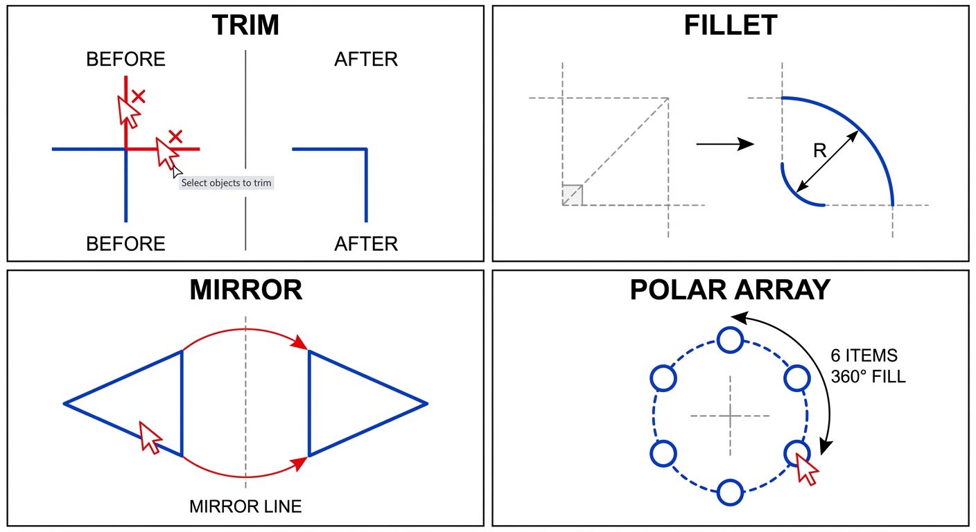
Mirror (MI)
Creates a reverse copy of the object across a specified line of symmetry.
- Mirror Line: Defined by two points.
- Erase Source Object? (Yes/No): Choose 'No' to keep both sides (butterfly effect).
Trim (TR)
Trims objects to meet the edges of other objects.
- Cutting Edges: The boundary lines that stop the trim.
- Object to Trim: The portion of the line to be removed.
- Note in newer AutoCAD: Quick mode automatically detects boundaries.
Scale (SC)
Enlarges or reduces selected objects uniformly.
- Base Point: The point from which the object grows/shrinks.
- Scale Factor:
> 1: Enlarges object.< 1: Shrinks object (e.g., 0.5 is half size).
4.3 Advanced Modify Tools
Fillet (F)
Rounds and fillets the edges of objects.
- Procedure: Command
F-> TypeR(Radius) -> Enter value -> Select two lines. - Tip: Using Radius = 0 creates a sharp corner (trims/extends lines to meet).
Chamfer (CHA)
Bevels the edges of objects (angled cut).
- Procedure: Command
CHA-> Select Distance (D) -> Enter Dist 1 and Dist 2 -> Select two lines.
Array (AR)
Creates multiple copies of objects in a pattern.
- Rectangular Array: Distributes objects in Rows and Columns.
- Polar Array: Distributes objects in a circular pattern around a center point.
- Path Array: Distributes objects along a spline or polyline.
5. Hands-on Practice: 2D Drawing Workflow
To execute an orthographic projection in AutoCAD, follow this structured approach:
-
Setup:
- Set
UNITS(usually Millimeters or Inches). - Set
LIMITS(e.g., 0,0 to 297,210 for A4). - Turn on
ORTHOmode (F8) andOSNAP(F3).
- Set
-
Layer Management: Create layers for organization:
- Outline: White/Black, Continuous, 0.5mm weight.
- Construction: Grey, Continuous, Default weight (Turn off later).
- Hidden: Yellow, Hidden linetype.
- Center: Red, Center linetype.
- Dimensions: Green, Continuous.
-
Drawing Construction:
- Use Construction Lines (
XLINE) to create a grid for Front, Top, and Side views ensuring alignment. - Draw the Front View first using
LINE,CIRCLE, etc. - Use vertical
XLINEorRAYcommands to project widths to the Top View. - Use horizontal
XLINEorRAYto project heights to the Side View. - Use a 45-degree miter line starting from the intersection of the view planes to transfer depth from Top to Side view.
- Use Construction Lines (
-
Refinement:
- Trim excess construction lines.
- Change line properties (switch internal hole lines to "Hidden" layer).
- Add Center lines for circles and symmetry.
-
Finalize:
- Apply Dimensions (Linear, Radius, Diameter).
- Add Text labels (FRONT VIEW, TOP VIEW).