Unit 2 - Notes
Unit 2: Projection of Points and Lines
1. Introduction and Principles of Orthographic Projections
1.1 Fundamentals of Projection
Projection is defined as the representation of an object on a two-dimensional plane (a sheet of paper or screen) as viewed by an observer. In Engineering Drawing, Orthographic Projection is the standard method used for technical communication.
- Principle: Projectors (imaginary lines of sight) are parallel to each other and perpendicular to the Plane of Projection.
- Reference Planes:
- Horizontal Plane (HP): The reference plane that is horizontal (like the floor). The view obtained on the HP is called the Top View (TV) or Plan.
- Vertical Plane (VP): The reference plane that is vertical (like a wall). The view obtained on the VP is called the Front View (FV) or Elevation.
- XY Line (Reference Line): The line of intersection between the HP and VP.
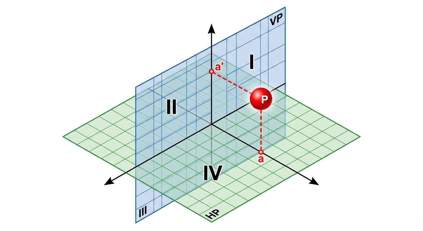
1.2 The System of Quadrants
The intersection of the HP and VP divides the space into four quadrants. The position of an object is defined relative to these planes.
- First Quadrant: Above HP, In front of VP. (Used in First Angle Projection - European/Indian Standard).
- Second Quadrant: Above HP, Behind VP.
- Third Quadrant: Below HP, Behind VP. (Used in Third Angle Projection - US Standard).
- Fourth Quadrant: Below HP, In front of VP.
Note: In orthographic drawing, after projecting the views, the HP is always rotated clockwise to align with the VP on the 2D sheet.
2. Orthographic Projection of Points
A point has no dimensions; it only has position. The notation convention is crucial:
- Actual Point: Capital letters (e.g., A, B).
- Front View (on VP): Lowercase letters with a prime/dash (e.g., a', b').
- Top View (on HP): Lowercase letters (e.g., a, b).
Summary of Point Positions
| Position of Point | Front View (Relative to XY) | Top View (Relative to XY) |
|---|---|---|
| Above HP | Above XY | N/A |
| Below HP | Below XY | N/A |
| In front of VP | N/A | Below XY |
| Behind VP | N/A | Above XY |
Example (First Angle):
If Point A is 20mm above HP and 30mm in front of VP:
- a' (FV): 20mm above the XY line.
- a (TV): 30mm below the XY line.
- The line connecting a and a' is a vertical line perpendicular to XY.
3. Orthographic Projection of Lines
A line is the shortest distance between two points. The projection of a line depends on its orientation relative to the HP and VP.
3.1 Orientation Cases
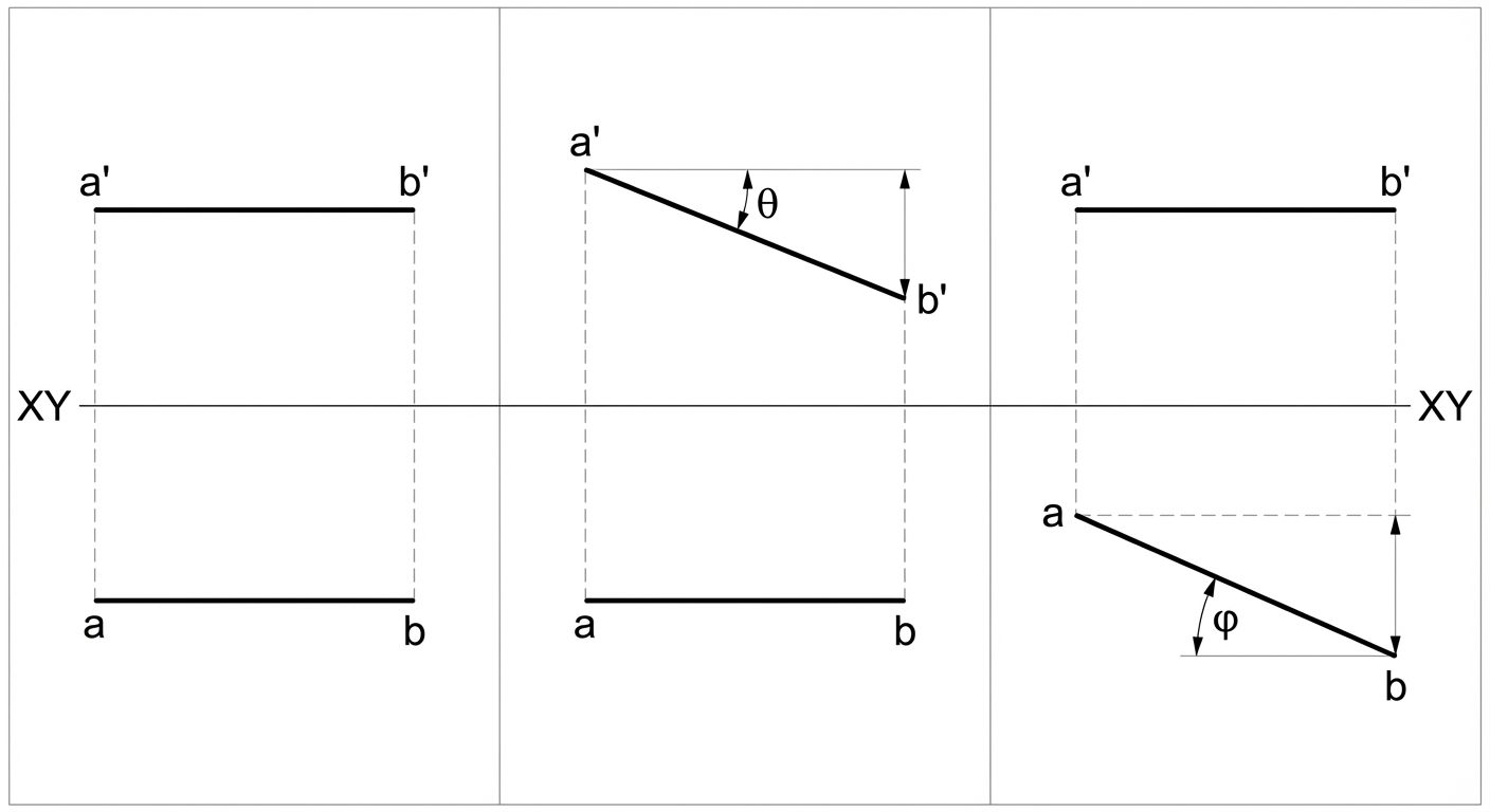
- Line Parallel to both HP and VP:
- FV: Parallel to XY (Shows True Length).
- TV: Parallel to XY (Shows True Length).
- Line Perpendicular to HP (and parallel to VP):
- FV: Vertical line perpendicular to XY (Shows True Length).
- TV: A point.
- Line Perpendicular to VP (and parallel to HP):
- FV: A point.
- TV: Vertical line perpendicular to XY (Shows True Length).
- Line Inclined to HP and Parallel to VP:
- FV: Inclined to XY at angle (Shows True Length).
- TV: Parallel to XY, shorter than True Length (Apparent Length).
- Line Inclined to VP and Parallel to HP:
- FV: Parallel to XY, shorter than True Length.
- TV: Inclined to XY at angle (Shows True Length).
3.2 Concept of Traces
Traces are the points where a line (or its extension) intersects the reference planes.
- HT (Horizontal Trace): The point where the line meets the HP. In the Front View, the line meets the XY line at a point (h'). The HT is located on a projector dropped from h'.
- VT (Vertical Trace): The point where the line meets the VP. In the Top View, the line meets the XY line at a point (v). The VT is located on a projector erected from v.
4. AutoCAD Commands and Geometries
AutoCAD is a vector-based drafting software. Commands can be executed via the Ribbon, Toolbar, or Command Line (Aliases).
4.1 Basic Drawing Commands
LINE (Alias: L)
Draws individual line segments.
- Usage: Type
L> Enter. Specify start point (click or type coords) > Specify next point. - Coordinate Systems:
- Absolute:
X,Y(e.g., 10,20) - Relative Rectangular:
@dX,dY(e.g., @20,0 means 20 units right). - Relative Polar:
@Length<Angle(e.g., @50<45).
- Absolute:
CIRCLE (Alias: C)
Creates circles based on various inputs.
- Methods:
- Center, Radius (Default).
- Center, Diameter.
- 2P (2 Point), 3P (3 Point).
- TTR (Tangent, Tangent, Radius).
ARC (Alias: A)
Draws a portion of a circle.
- Default: 3-Point Arc.
- Common Method: Start, Center, End (Counter-clockwise direction is positive).
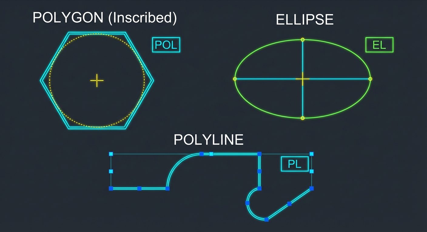
POLYLINE (Alias: PL)
Creates a 2D line consisting of connected line segments and arc segments that act as a single object.
- Difference from Line: A rectangle made with
LINEis 4 objects; a rectangle made withPLINEis 1 object. Polyline also supports width (w).
4.2 Geometric Shapes
RECTANGLE (Alias: REC)
- Input: Specify first corner > Specify other corner (or dimensions).
- Options: Chamfer, Fillet, Width (can be set before drawing).
POLYGON (Alias: POL)
Creates an equilateral closed polyline.
- Steps:
- Enter number of sides (3 to 1024).
- Specify center.
- Choose option:
- Inscribed in circle (I): Vertex touches the imaginary circle radius.
- Circumscribed about circle (C): Midpoint of edge touches the radius.
- Alternative: Edge method (defines length of one side).
ELLIPSE (Alias: EL)
- Axis End Method: Specify one endpoint of axis 1 > Second endpoint > Distance to other axis end.
- Center Method: Specify center > Endpoint of axis 1 > Endpoint of axis 2.
5. Dimensioning and Styles in AutoCAD
Dimensioning is the process of adding measurement annotations to the drawing.
5.1 Dimension Commands
- Linear (
DLI): Horizontal or vertical distances. - Aligned (
DAL): Distances parallel to an inclined line. - Radius (
DRA) / Diameter (DDI): For circles and arcs. - Angular (
DAN): Angle between two lines.
5.2 Dimension Style Manager (DIMSTYLE / D)
Used to customize the appearance of dimensions.
- Lines Tab: Color, linetype, lineweight, extend beyond ticks, baseline spacing.
- Symbols and Arrows: Arrowheads (Closed filled, Architectural tick), arrow size, center marks.
- Text: Text style, color, height, placement (centered/above).
- Primary Units: Unit format (Decimal/Architectural), Precision (0.00), Suffix/Prefix.
6. Hands-on Practice: Workflow for Unit 2 Problems
When solving a projection of lines problem in AutoCAD, follow this workflow:
-
Setup:
- Command:
UNITS(Set to Millimeters, Precision 0.00). - Command:
LIMITS(Set drawing area, e.g., 0,0 to 297,210 for A4). - Command:
Z>A(Zoom All).
- Command:
-
Reference Line:
- Enable Ortho Mode (F8).
- Draw the XY line horizontally using
LINE. Change color/layer (usually standard white).
-
Projections:
- Projections of Points: Use
POINTcommand (change point style withDDPTYPE) or small crosses usingLINE. - Projectors: Use a faint color (e.g., gray) for projection lines connecting Top View and Front View. These must be perfectly vertical (Ortho On).
- Projections of Points: Use
-
Drawing Inclined Lines:
- Use Polar Coordinates.
- Example: Line 50mm long, inclined to HP.
- Command:
L> Click start point on XY >@50<30.
-
Final Polish:
- Use
LWEIGHT(Lineweight) to make the actual object lines (a-b, a'-b') thicker (e.g., 0.30mm) than the XY line and projector lines (0.15mm). - Add dimensions using
DIMLINEARandDIMANGULAR. - Add text labels (a, a', X, Y, HP, VP) using
MTEXT.
- Use