Unit 1 - Notes
Unit 1: Introduction to Engineering Drawing
1. Conceptual Framework of Drawing Instruments
Engineering drawing is the language of engineers, used to convey precise technical details. Before Computer-Aided Design (CAD), manual drafting relied on specific instruments to ensure accuracy.
Key Instruments and Uses
- Drawing Board: A flat, smooth surface (usually made of seasoned soft wood) used to mount the drawing sheet.
- Mini-Drafter: A versatile tool that combines the functions of a T-square, set-square, scale, and protractor. It uses a parallelogram mechanism to keep the ruler parallel to a reference edge anywhere on the board.
- Set Squares: Used for drawing lines at specific angles.
- Set Square: Draws , , and lines.
- - Set Square: Draws , , , etc.
- Compass:
- Large Compass: For drawing circles with large radii.
- Bow Compass: Features an adjusting screw/nut for precise small circles; prevents legs from sliding.
- Dividers: Used to transfer dimensions from the scale to the drawing or to divide lines into equal parts.
- Pencils (Grades):
- H, 2H: Hard pencils used for construction lines, center lines, and guide lines (thin and light).
- HB, H: Medium grade used for visible outlines, lettering, and dimensions (thick and dark).
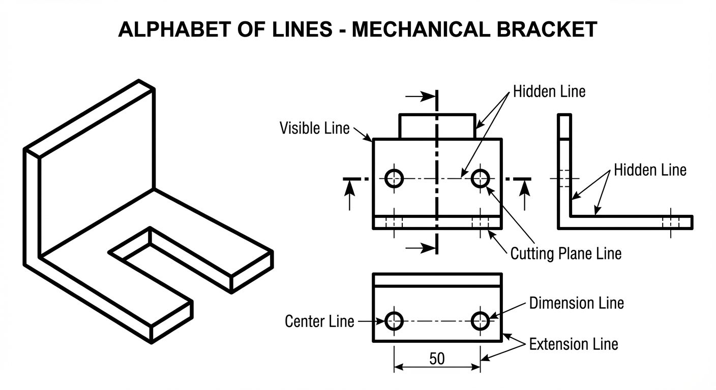
2. Line Types (The Alphabet of Lines)
In engineering drawing, different line styles represent specific features of an object. This standardization prevents ambiguity.
| Line Type | Appearance | Application/Usage | Pencil Grade |
|---|---|---|---|
| Visible / Object Line | Thick, continuous | Represents visible edges and outlines of the object. | H / HB |
| Hidden Line | Medium, dashed (short dashes) | Represents edges or surfaces hidden behind other surfaces. | 2H |
| Center Line | Thin, chain (long-short-long) | Indicates axes of symmetry, centers of circles/holes. | 2H |
| Construction Line | Very thin, continuous | Preliminary work, layout lines. | 3H / 4H |
| Dimension Line | Thin, continuous with arrows | Indicates the extent of a dimension. | 2H |
| Extension Line | Thin, continuous | Extends from the object to hold the dimension line. | 2H |
| Cutting Plane Line | Thick, chain (thick ends) | Shows where an imaginary cut is made for sectional views. | HB |
3. Dimensioning
Dimensioning is the process of specifying the size and location of features on a drawing.
Elements of Dimensioning
- Extension Lines: Extend from the object (leaving a 1-2mm gap) to enclose the dimension.
- Dimension Lines: Drawn between extension lines, ending with arrowheads.
- Arrowheads: Standard ratio is 3:1 (Length : Width). They should be filled and sharp.
- Leader Lines: Used to connect a note or dimension (like a radius) to a feature. Drawn at an angle (usually , , or ).
Systems of Dimensioning
- Aligned System: Dimensions are placed perpendicular to the dimension line. Horizontal dimensions are read from the bottom; vertical dimensions are read from the right-hand side.
- Unidirectional System: All dimensions are placed vertically so they can be read from the bottom of the sheet. The dimension line is broken in the middle to insert the text.
4. Single Stroke Vertical Gothic Lettering
Legibility is the primary requirement for lettering in engineering drawings. "Single Stroke" means the thickness of the line is determined by the width of the pencil point, not by drawing an outline and filling it in.
General Rules (IS 9609 / SP 46)
- Style: Vertical, capital letters (Gothic style means uniform line thickness).
- Aspect Ratio: Most letters use a width-to-height ratio of 5:7 or 7:10.
- Exceptions:
MandWare wider (Ratio ~ 6:7 or 8:10).Iis the thinnest.
- Spacing: Space between letters should appear visually equal (area method), not mechanically equal. Space between words equals the height of one letter.
5. Scales
Scales are used to represent large objects on small paper (Reduction) or small objects on large paper (Enlargement).
Representative Fraction (R.F.):
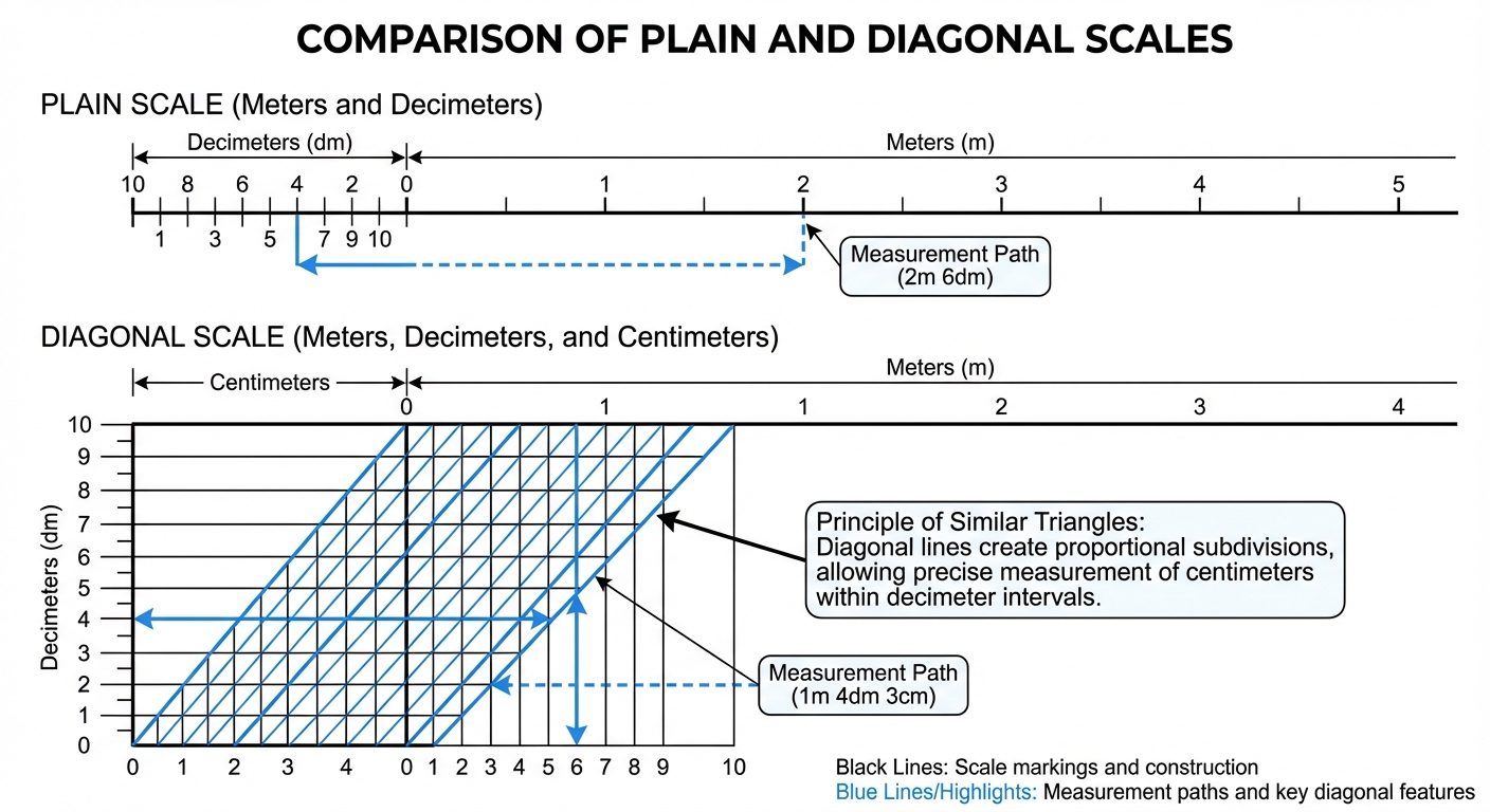
Plain Scale
- Purpose: Measures up to two consecutive units (e.g., Meters and Decimeters, or Centimeters and Millimeters).
- Construction: A line is divided into a number of equal main parts (first unit). The first division is subdivided into smaller parts (second unit).
Diagonal Scale
- Purpose: Measures up to three consecutive units (e.g., Meters, Decimeters, and Centimeters) or reads to a higher degree of accuracy (two decimal places).
- Principle: Based on the principle of Similar Triangles. A short vertical line is divided into equal parts, and diagonal lines are drawn to subdivide the horizontal divisions further.
6. Introduction to AutoCAD Interface
AutoCAD (Computer-Aided Design) replaces manual drafting tools with digital precision.
Key Interface Elements
- Application Menu (Big Red A): File operations (New, Open, Save, Print).
- Ribbon: The panel containing tool icons organized by tabs (Home, Insert, Annotate).
- Command Line: The area at the bottom where you type commands (e.g.,
LINE,CIRCLE) and see prompts. - UCS Icon (User Coordinate System): Shows the X and Y orientation.
- Crosshairs: The cursor used to draw and select objects.

Basic Setup Commands
- UNITS (
UN): Sets the drawing units (Decimal, Architectural) and precision ($0.00$). - LIMITS: Defines the virtual drawing boundary (lower-left corner usually 0,0).
- ZOOM (
Z): Controls the magnification of the view.- Zoom All: Shows the entire defined limit area.
- Zoom Extents: Zooms to fit all drawn objects on the screen.
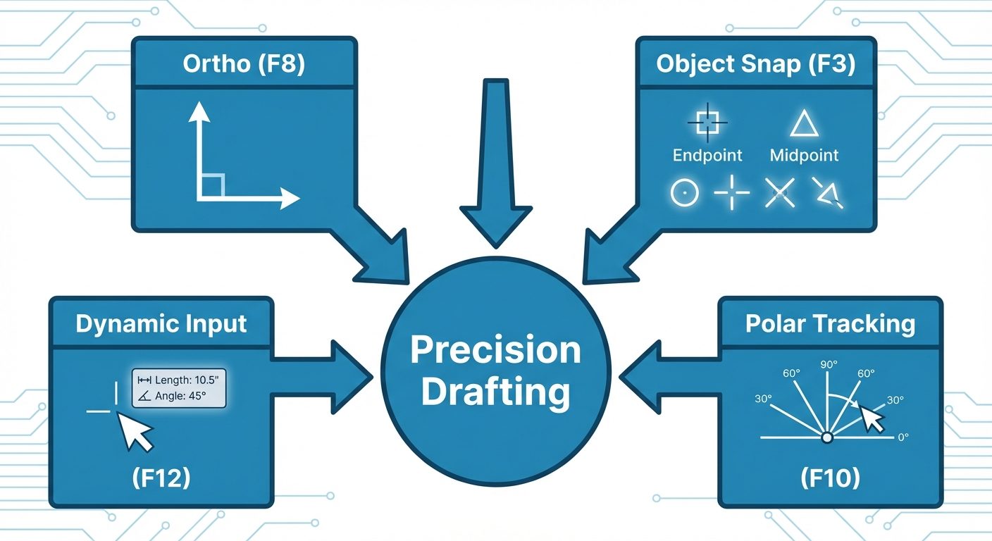
Navigation and Drafting Aids
- OSNAP (Object Snap - F3): Crucial for precision. It forces the cursor to snap to geometric points on an object, such as:
- Endpoint: Ends of lines/arcs.
- Midpoint: Center of a line.
- Center: Geometric center of circle/arc.
- Intersection: Where two objects cross.
- ORTHO Mode (F8): Restricts cursor movement to horizontal () and vertical () directions only.
- UCS (User Coordinate System): Defines the origin (0,0,0) and the orientation of the X, Y, and Z axes. Users can move the UCS to align with slanted surfaces.
Functional Keys (F-Keys) Cheat Sheet
Standard AutoCAD toggle keys located on the keyboard:
| Key | Function | Description |
|---|---|---|
| F1 | Help | Opens AutoCAD help documentation. |
| F2 | Expanded History | Toggles the command history window. |
| F3 | OSNAP | Toggles Object Snap on/off. |
| F7 | Grid | Toggles the background grid display. |
| F8 | ORTHO | Toggles Orthogonal mode (Straight lines only). |
| F9 | Snap Mode | Restricts cursor movement to specific grid intervals. |
| F10 | Polar Tracking | Restricts cursor to specified angles (non-90 degree). |
| F12 | Dynamic Input | Displays command input near the cursor. |