Practical 2
Practical 2: KVL Voltage Hunt
1. Aim/Objective
To verify Kirchhoff's Voltage Law (KVL) in a DC resistive network by measuring voltage drops across various components in closed loops and comparing the algebraic sum with theoretical predictions.
2. Apparatus/Components Required
| S.No | Component/Equipment | Specification | Quantity |
|---|---|---|---|
| 1 | DC Regulated Power Supply (RPS) | 0-30V, 1A (Dual Channel preferred) | 1 |
| 2 | Digital Multimeter (DMM) | Standard Laboratory Grade | 1 |
| 3 | Breadboard | Standard size | 1 |
| 4 | Resistors (Fixed) | , , (1/4 Watt) | 1 each |
| 5 | Connecting Wires | Single strand hook-up wires | As req. |
3. Theory
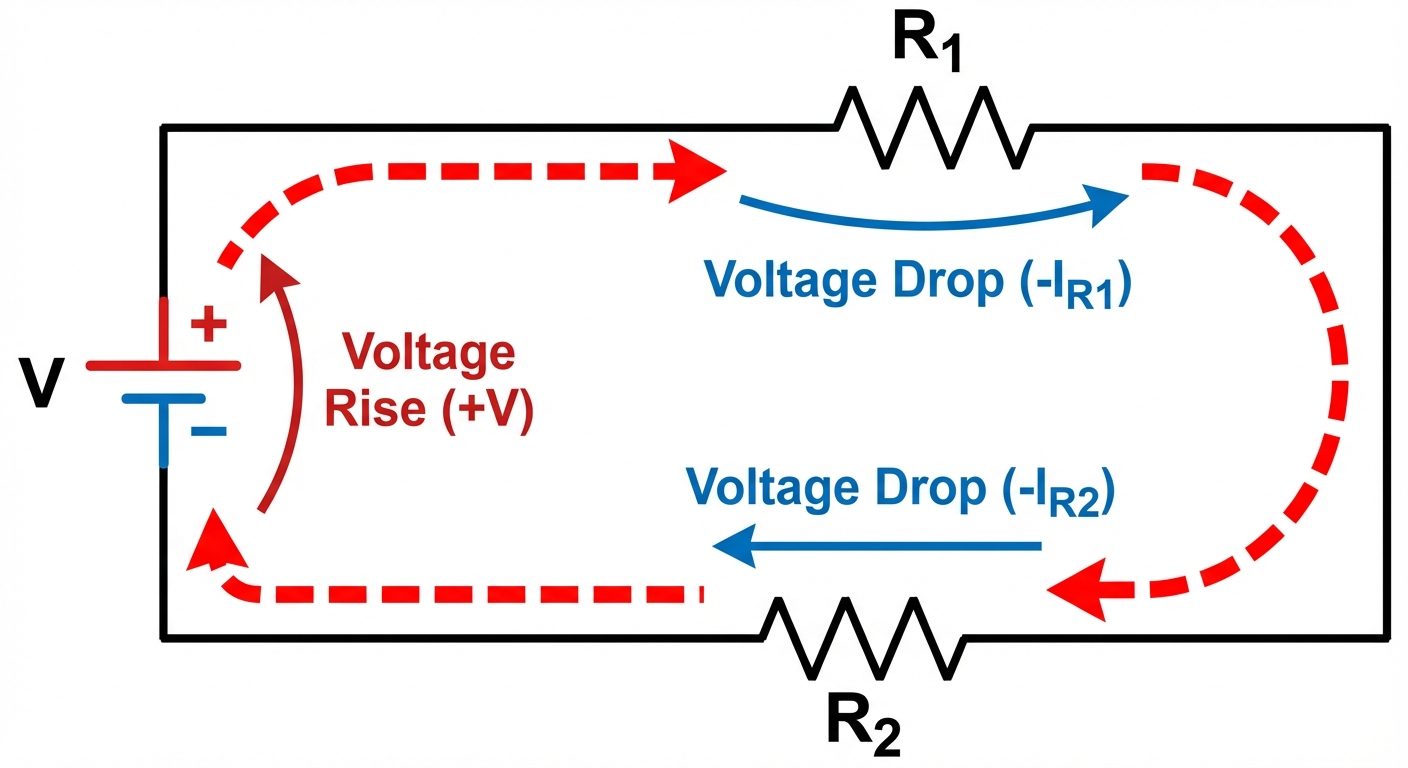
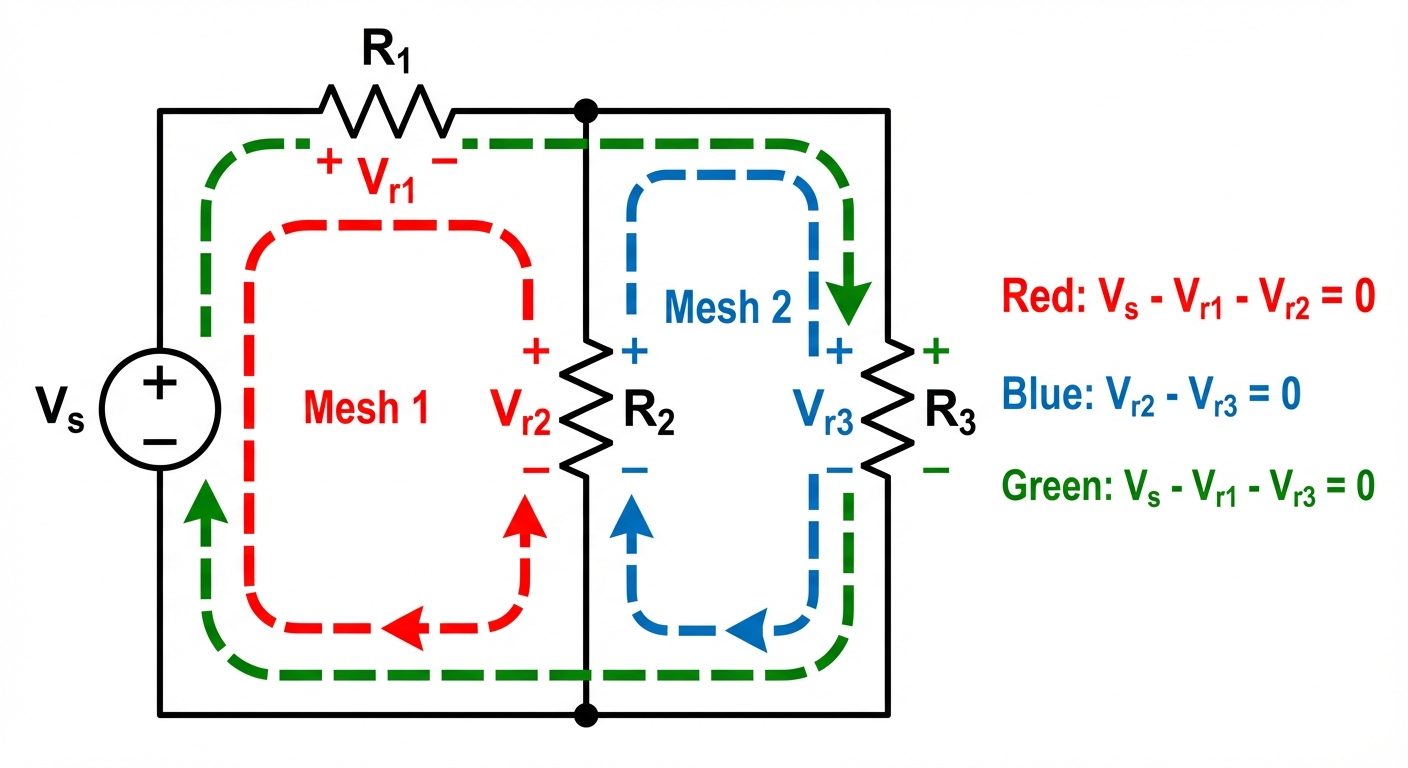
Kirchhoff's Voltage Law (KVL) states that the algebraic sum of all voltages around any closed loop (mesh) in a circuit is equal to zero. This is a manifestation of the Law of Conservation of Energy.
Mathematically:
Sign Convention for Analysis:
- Voltage Rise: Moving from negative (-) to positive (+) terminal (e.g., traversing a battery from - to +). Value is taken as Positive.
- Voltage Drop: Moving from positive (+) to negative (-) terminal (e.g., current flowing through a resistor). Value is taken as Negative.
In a practical "Voltage Hunt," we measure the potential difference across every component. If we traverse a loop and sum these values (respecting polarity), the result should ideally be zero.
4. Circuit Diagram / Setup
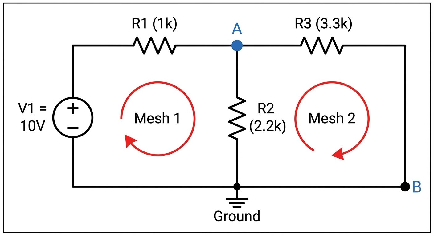
We will utilize a T-Network circuit which provides two distinct meshes for analysis.
Circuit Components:
- V1: 10V DC Source
- R1: (Series arm)
- R2: (Shunt/Shared arm)
- R3: (Output arm)
5. Procedure
- Preparation: Check the resistance values of , , and using the Digital Multimeter (Ohmmeter mode) and record the actual measured values.
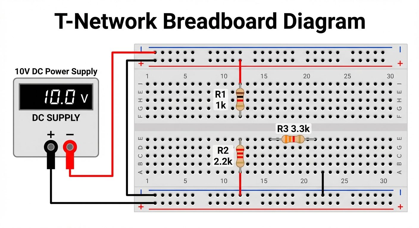
- Circuit Assembly: Connect the circuit on the breadboard as shown in the breadboard layout diagram. Ensure all connections are tight.
- Power Up: Switch on the Regulated Power Supply (RPS) and set the output voltage () to exactly 10V.
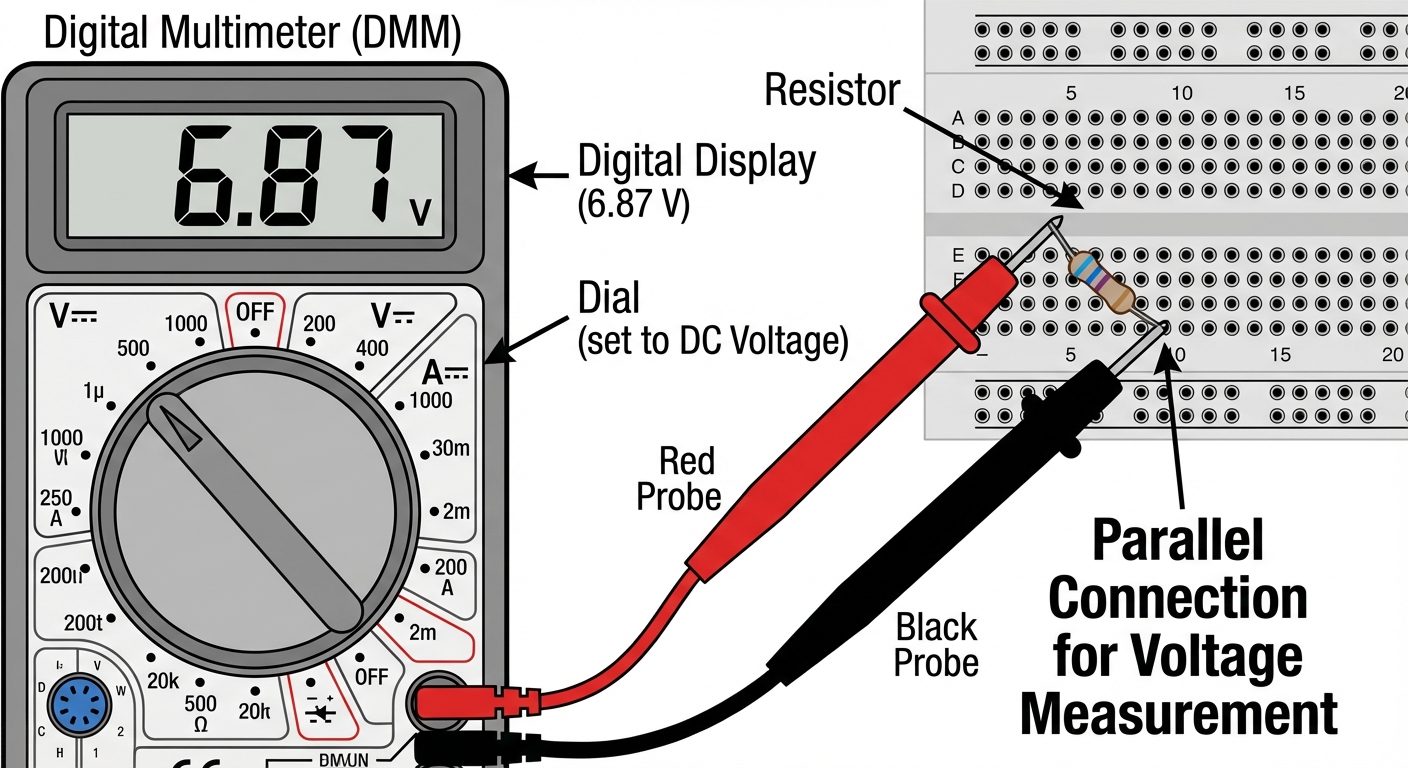
- Measurement Strategy: You will measure voltage drops across every element. Crucial: Always place the Red Probe of the DMM at the point where current enters the component and the Black Probe where current leaves to get a positive reading for a drop.
- Measure Loop 1 (Mesh 1):
- Measure voltage across Source ().
- Measure voltage across ().
- Measure voltage across ().
- Measure Loop 2 (Mesh 2):
- Measure voltage across (). Note: This is the shared branch.
- Measure voltage across ().
- Verification: Record all readings with proper signs in the observation table.
6. Observations & Readings
Input Voltage (): ___ V (Set to approx 10V)
Resistor Values (Measured):
- : ____
- : ____
- : ____
Table 1: Voltage Drops
| Component | Theoretical Voltage (V) | Practical (Measured) Voltage (V) |
|---|---|---|
| Calculate in Section 7 | ||
| Calculate in Section 7 | ||
| Calculate in Section 7 |
Table 2: KVL Verification (Algebraic Sum)
| Loop Path | Equation | Calculation (Sum of Measured Values) | Result | Ideally |
|---|---|---|---|---|
| Mesh 1 | _____ V | 0 V | ||
| Mesh 2 | _____ V | 0 V | ||
| Outer Loop | _____ V | 0 V |
Note: In Mesh 2, if taking clockwise direction, we go "up" against the current in R2 (Rise) and "down" with current in R3 (Drop). So equation is .
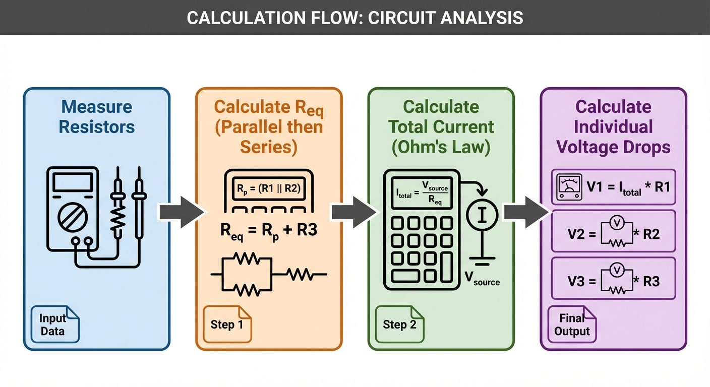
7. Calculations
Step 1: Calculate Total Resistance ()
and are in parallel (since goes to ground and goes to ground in this T-config, effectively parallel connected to node after ).
Step 2: Calculate Total Current ()
Step 3: Theoretical Voltage Drops
- Voltage at Node A () =
- Since and are in parallel connected to Node A:
Step 4: % Error Calculation
8. Result
The Kirchhoff’s Voltage Law (KVL) has been verified for the given resistive network.
- Mesh 1 Sum: The algebraic sum of voltages in Mesh 1 was found to be ______ V (approx 0V).
- Mesh 2 Sum: The algebraic sum of voltages in Mesh 2 was found to be ______ V (approx 0V).
Small deviations from zero are attributed to tolerance of resistors, contact resistance of the breadboard, and internal resistance of the multimeter.
9. Viva Questions
-
Q: On what fundamental principle is KVL based?
- A: KVL is based on the Law of Conservation of Energy. It states that energy gained by charge in a source must be dissipated across passive elements in a closed loop.
-
Q: Why must the DMM be connected in parallel to measure voltage?
- A: Voltage is a potential difference between two points. Connecting in parallel allows the meter to sample the energy difference across the component without interrupting the circuit path. Ideally, a voltmeter has infinite resistance.
-
Q: If you traverse a resistor opposite to the direction of current, is it a voltage rise or drop?
- A: It is considered a Voltage Rise (+), because you are moving from a lower potential to a higher potential.
-
Q: Can KVL be applied to an open loop?
- A: No, KVL specifically applies to closed conducting paths (loops or meshes) where the starting and ending point are the same.
-
Q: What happens if you sum the voltages but get a value significantly non-zero (e.g., 2V)?
- A: This indicates an error: loose connections, a faulty component, incorrect measurement polarity, or a battery that is draining under load.
