Practical 1
Practical 1: The Electronics Expedition
1. Aim/Objective
To identify, categorize, and familiarize with basic electronic active and passive components, breadboards (trainer modules), input sources (DC Power Supply, Function Generator), and measuring/display instruments (Digital Multimeter, CRO/DSO).
2. Apparatus/Components Required
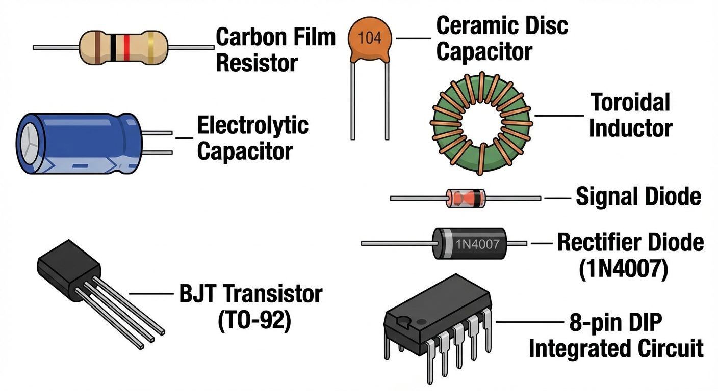
- Passive Components: Assorted Resistors (Carbon film), Capacitors (Ceramic disk, Electrolytic), Inductors, Transformers.
- Active Components: Diodes (1N4007), Zener Diodes, Transistors (BJT BC547), Integrated Circuits (e.g., 555 Timer, 7400 series).
- Prototyping Hardware: Breadboard / Analog-Digital Trainer Kit, Connecting wires (single strand).
- Input Sources: Regulated DC Power Supply (0-30V), Function Generator (1Hz - 1MHz).
- Measuring Instruments: Digital Multimeter (DMM), Cathode Ray Oscilloscope (CRO) or Digital Storage Oscilloscope (DSO).
3. Theory
A. Electronic Components
Components are classified into two categories:
- Passive Components: Devices that cannot introduce net energy into the circuit. They rely on a source of power.
- Resistor (R): Opposes the flow of current. Unit: Ohm ().
- Capacitor (C): Stores electrical energy in an electric field. Unit: Farad (F).
- Inductor (L): Stores electrical energy in a magnetic field. Unit: Henry (H).
- Active Components: Devices capable of amplifying signals or switching currents. They require an external source to operate.
- Diode: Allows current to flow in only one direction (rectification).
- Transistor: A semiconductor device used to amplify or switch electrical signals and power.
- Integrated Circuit (IC): A set of electronic circuits on one small flat piece (or "chip") of semiconductor material.
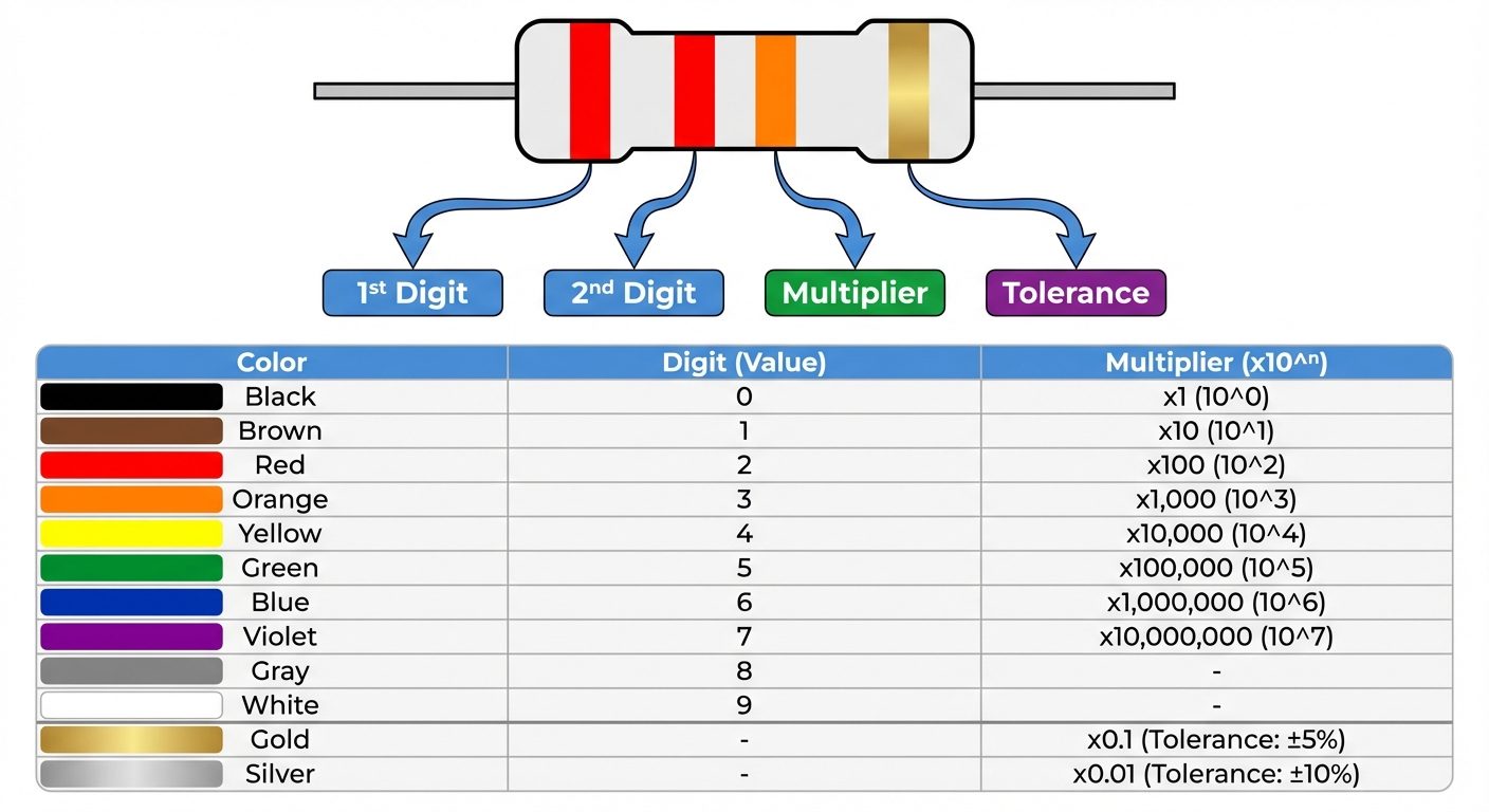
B. Resistor Color Coding
Carbon film resistors use color bands to indicate their resistance value.
- 4-Band System: Band 1 (1st Digit), Band 2 (2nd Digit), Band 3 (Multiplier), Band 4 (Tolerance).
- Formula:
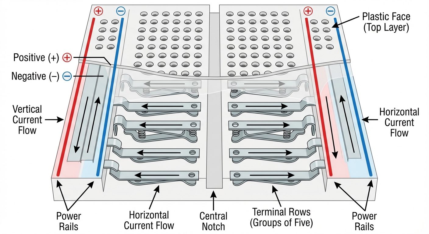
C. The Breadboard (Prototyping Board)
A breadboard is used for building temporary circuits. It consists of:
- Bus Strips: Located on the sides, usually used for power supply connections. All holes in a vertical column are connected internally.
- Terminal Strips: Located in the center. Holes are connected horizontally in rows of five. A central ravine separates the two sides, sized to fit ICs.
4. Input Sources and Display Devices Setup
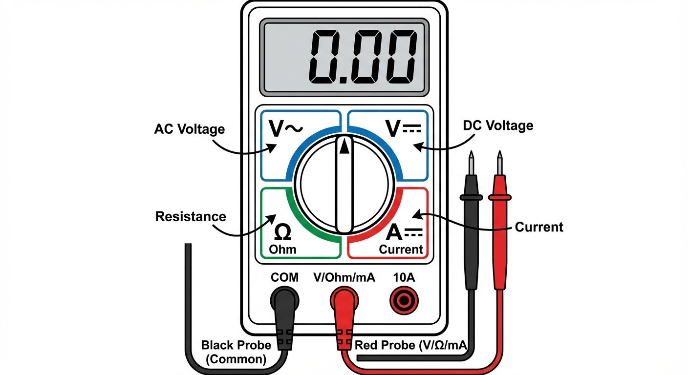
A. Digital Multimeter (DMM)
A DMM is a versatile instrument used to measure Voltage (AC/DC), Current (AC/DC), Resistance, and Continuity.
- Voltmeter Mode: Connect in Parallel with the component.
- Ammeter Mode: Connect in Series with the circuit path.
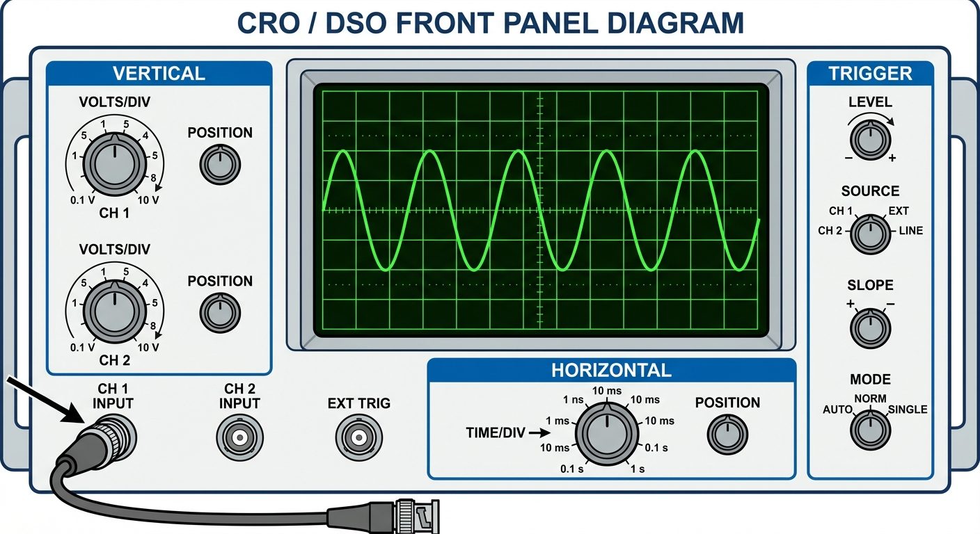
B. Cathode Ray Oscilloscope (CRO) / DSO
Used to observe the change of an electrical signal over time (Voltage vs. Time).
- X-axis: Represents Time (Time/Div knob).
- Y-axis: Represents Voltage/Amplitude (Volts/Div knob).
5. Procedure
Part A: Identification and Reading of Resistors
- Select 5 different resistors from the assortment.
- Observe the color bands on each resistor.
- Calculate the theoretical resistance using the color code chart.
- Switch the DMM to Resistance () mode.
- Connect the multimeter probes across the resistor leads (polarity does not matter).
- Record the measured value and calculate the percentage error.
Part B: Familiarization with Regulated Power Supply (RPS)
- Switch on the Regulated DC Power Supply.
- Set the DMM to DC Voltage () mode.
- Connect the Red probe of the DMM to the Positive (+) terminal of the RPS and Black probe to the Negative (-) terminal.
- Adjust the voltage knob on the RPS to set values (e.g., 5V, 10V, 12V) and verify the reading on the DMM.
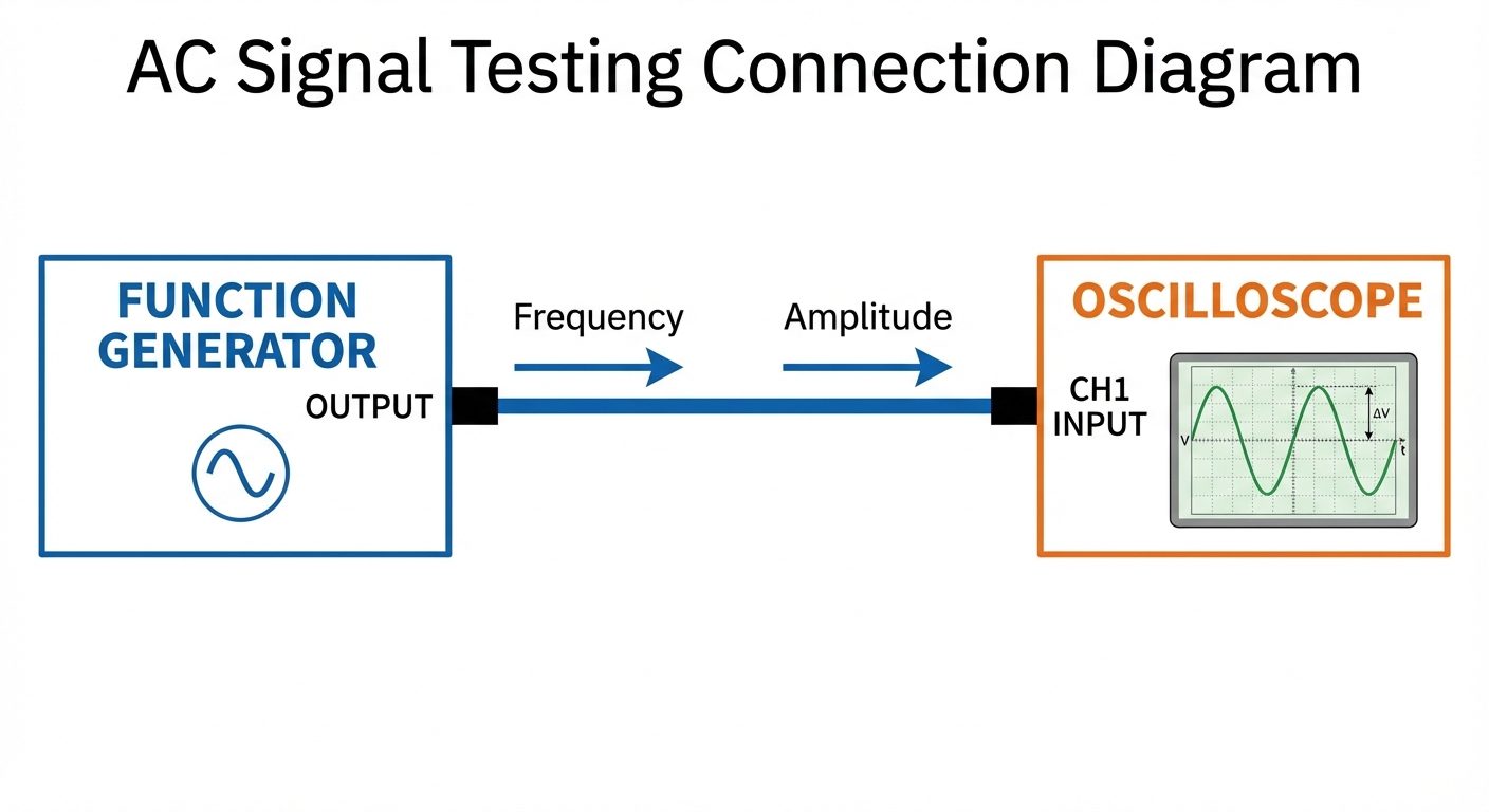
Part C: Familiarization with Function Generator and CRO
- Switch on the Function Generator and CRO.
- Connect the output of the Function Generator to Channel 1 of the CRO using a BNC probe.
- Set the Function Generator to produce a Sine Wave at 1 kHz frequency.
- Press Autoset (on DSO) or adjust Volts/Div and Time/Div knobs (on Analog CRO) until a stable wave is visible.
- Observe the waveform. Change the wave type to Square and Triangular and observe the change on the display.
- Measure the Peak-to-Peak voltage () and Time Period () from the screen grid.
6. Observations and Tables
Table 1: Resistor Color Code Verification
| Sr. No. | Band 1 | Band 2 | Band 3 (Multiplier) | Band 4 (Tolerance) | Calculated Value () | Measured Value () | % Error |
|---|---|---|---|---|---|---|---|
| 1 | Brown | Black | Red | Gold | 2% | ||
| 2 | Red | Red | Red | Gold | |||
| 3 | Yellow | Violet | Orange | Silver |
Table 2: DC Source Verification
| Sr. No. | Voltage Set on Power Supply (V) | Voltage Measured on DMM (V) | Remark |
|---|---|---|---|
| 1 | 3.3 V | ||
| 2 | 5.0 V | ||
| 3 | 12.0 V |
7. Calculations
Percentage Error Calculation for Resistors:
Example Calculation:
If and :
8. Result
- Various electronic components (Resistors, Capacitors, Inductors, Diodes, Transistors) were identified successfully.
- Resistance values were calculated using color codes and verified using a Digital Multimeter.
- The breadboard internal connections were studied and understood.
- Input sources (DC Supply, Function Generator) and output devices (DMM, CRO) were successfully operated and verified.
9. Viva Questions
- What is the difference between active and passive components?
- Ans: Passive components (R, L, C) dissipate or store energy but cannot generate or amplify it. Active components (Transistors, Op-Amps) can amplify signals and require an external power source.
- Why do we use a breadboard?
- Ans: It allows for temporary prototyping and testing of circuits without soldering, making it easy to modify connections.
- What is the tolerance of a Gold band resistor?
- Ans: .
- How is an Ammeter connected in a circuit and why?
- Ans: An ammeter is connected in series because current remains the same in a series circuit, and the ammeter has very low internal resistance to avoid affecting the circuit.
- What does 'CRO' stand for and what does it measure?
- Ans: Cathode Ray Oscilloscope. It visualizes voltage amplitude with respect to time.
- What is the function of a Diode?
- Ans: A diode allows current to flow in only one direction (forward bias) and blocks it in the reverse direction.
- Identify the pins of a BJT (Transistor).
- Ans: Emitter (E), Base (B), and Collector (C).