Unit 5 - Notes
Unit 5: Isometric Views
1. Introduction
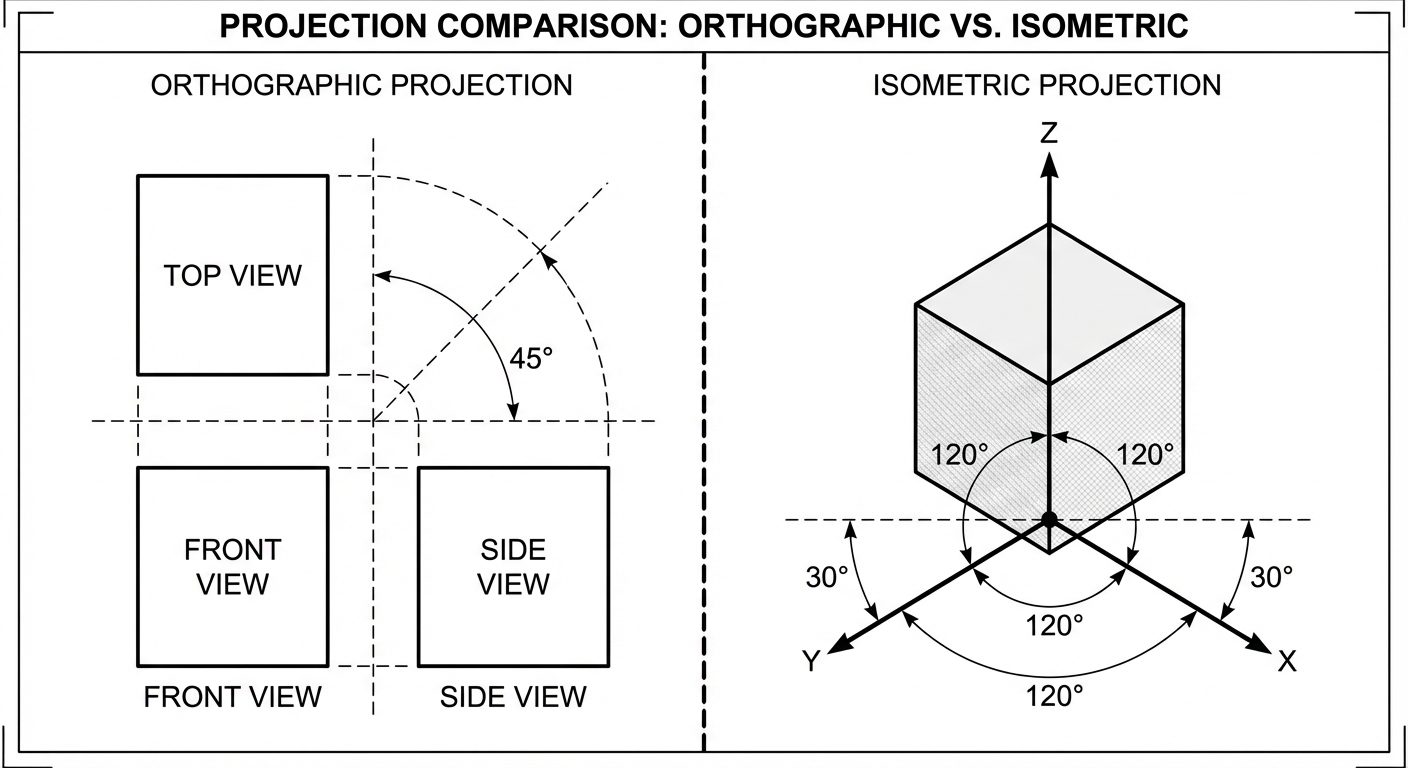
Isometric projection is a method of pictorial representation where a three-dimensional object is represented on a two-dimensional plane. It is a type of axonometric projection. The term "Isometric" is derived from the Greek words iso (equal) and metric (measure), meaning "equal measure."
In an isometric view, the three mutually perpendicular edges of a cube (length, width, and height) are equally inclined to the plane of projection. Consequently, they are foreshortened by the same amount.
Key Characteristics
- Three Axes: The three principal axes meet at a point and make an angle of with each other.
- Horizontal Alignment: One axis is usually vertical, while the other two recede at to the horizontal line.
- Scale: All dimensions along the isometric axes are measured using a specific scale (Isometric Scale) or true scale (for Isometric View).
2. Terminology
To construct isometric drawings accurately, one must understand the following terms:
Isometric Axes
The three lines meeting at a point and making an angle of with each other are called isometric axes.
- Vertical Axis: Represents height.
- Right Axis (): Usually represents length/width.
- Left Axis (): Usually represents width/length.
Isometric Lines
Any line that is parallel to one of the isometric axes is called an isometric line. Measurements can be made directly on these lines.
Non-Isometric Lines
Lines that are not parallel to the isometric axes are called non-isometric lines. These lines cannot be measured directly; their endpoints must be located using isometric coordinates.
- Example: The slant edge of a pyramid or the diagonal of a cube.
Isometric Planes
The planes representing the faces of the cube (formed by two isometric axes) are called isometric planes.
- Top Plane: Formed by the two axes.
- Left/Right Vertical Planes: Formed by the vertical axis and one axis.
3. Isometric Scale
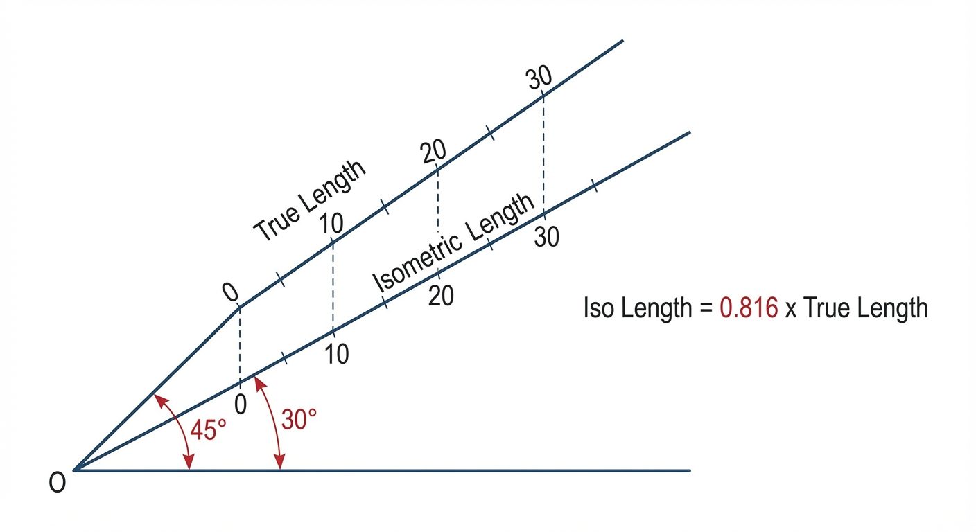
In a true isometric projection, the lines are foreshortened because the object is tilted relative to the viewing plane.
- Isometric View (Drawing): Drawn using the True Scale (actual dimensions). This is the standard practice in AutoCAD and most engineering sketches for visualization purposes.
- Isometric Projection: Drawn using the Isometric Scale.
Derivation of Isometric Scale
To convert true length to isometric length:
Formula:
4. Isometric Views of Solids
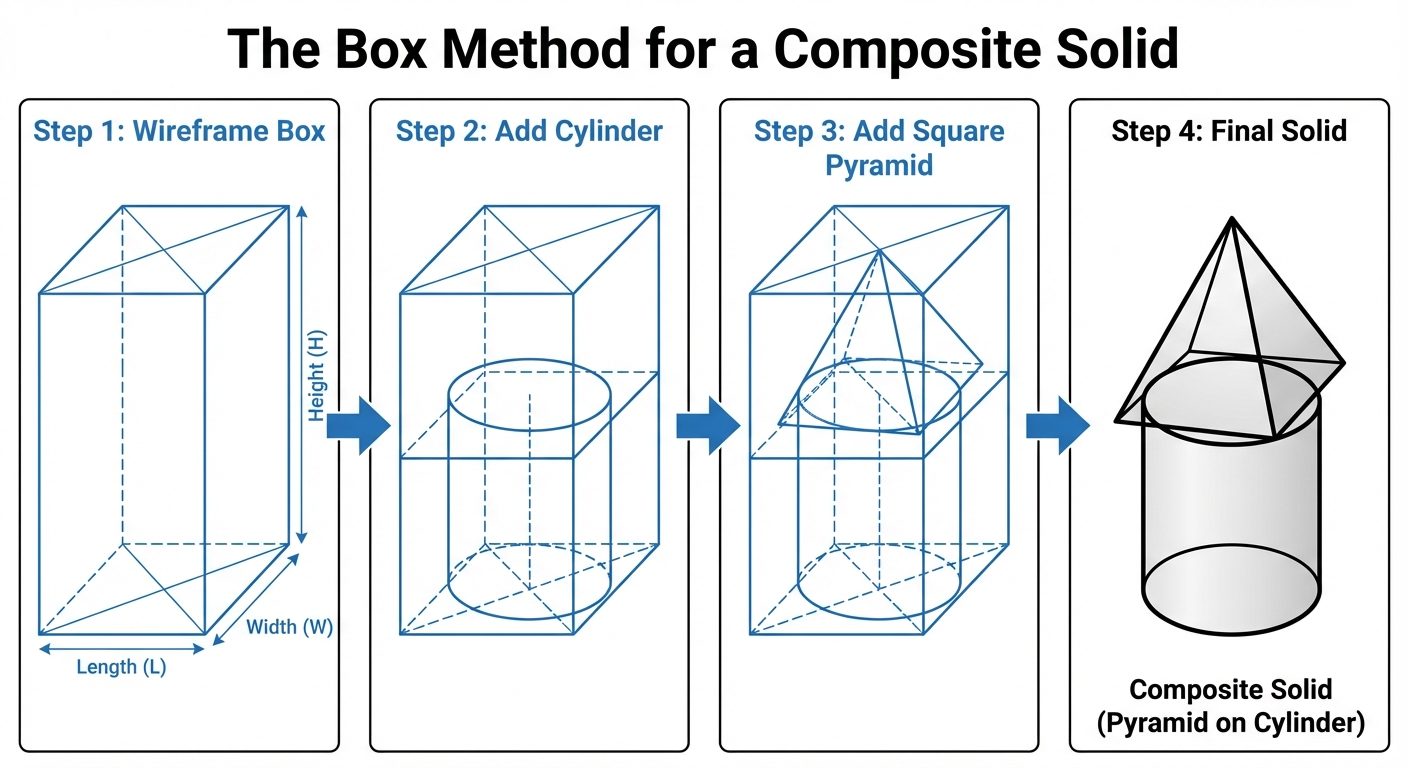
Solids are generally constructed using the Box Method (also known as the enclosing box method). This involves imagining the object enclosed in a rectangular box with dimensions equal to the overall length, width, and height of the object.
A. Isometric Views of Prisms
Prisms have rectangular faces and two parallel bases (e.g., square prism, hexagonal prism).
- Draw the isometric axes.
- Construct the base geometry on the appropriate isometric plane.
- Draw vertical lines (isometric lines) from the corners of the base equal to the height of the prism.
- Connect the top points to form the top face.
B. Isometric Views of Pyramids
Pyramids have a polygonal base and triangular faces meeting at a common apex.
- Enclose the Base: Draw the base of the pyramid in a square/rectangle box using isometric lines.
- Locate Center: Draw diagonals on the isometric base to find the center point.
- Axis Line: From the center point, draw a vertical line representing the axis height.
- Apex: The top of this line is the apex.
- Connect Edges: Join the apex to the corners of the base. These connecting lines are usually non-isometric lines.
C. One Object on Top of Another (Composite Solids)
Commonly referred to as stacked objects (e.g., a sphere on a cylinder, a pyramid on a cube).
- Draw the bottom solid first completely.
- Locate the center of the top face of the bottom solid.
- Construct the base of the second object centered on this point.
- Draw the second solid.
- Visibility: Erase or trim the lines of the bottom object that are hidden by the top object.
5. Dimensioning in Isometric Views
Dimensioning isometric drawings requires specific rules to maintain the 3D illusion. The Aligned System of dimensioning is used.
- Extension Lines: Must be drawn parallel to the isometric axes.
- Dimension Lines: Must be parallel to the object line being measured.
- Text Placement: Text should be aligned with the dimension line. In AutoCAD, text must also be "obliqued" (tilted) to lie in the isometric plane.
- Dimensions on the Left Plane: Text oblique angle .
- Dimensions on the Right Plane: Text oblique angle .
6. AutoCAD Commands for 3D Modeling
While 2D Isometric drafting uses the ISODRAFT command, true 3D modeling uses a different coordinate system and set of tools.
A. 3P UCS (3-Point User Coordinate System)
The World Coordinate System (WCS) is fixed. To draw on different faces of a 3D object, the UCS must be moved.
- Command:
UCS>3(3 Point). - Process:
- Specify new Origin (0,0,0).
- Specify a point on the positive X-axis.
- Specify a point on the positive Y-axis.
- Usage: Crucial for defining the "working plane" (e.g., drawing a circle on a slanted face).
B. Standard Shapes (Primitives)
AutoCAD provides pre-built 3D solids.
- BOX: Creates a rectangular prism.
- CYLINDER: Creates a cylinder with defined radius and height.
- CONE: Creates a cone (tapered or pointed).
- SPHERE: Creates a solid ball.
- WEDGE: Creates a triangular prism.
- TORUS: Creates a donut-shaped ring.
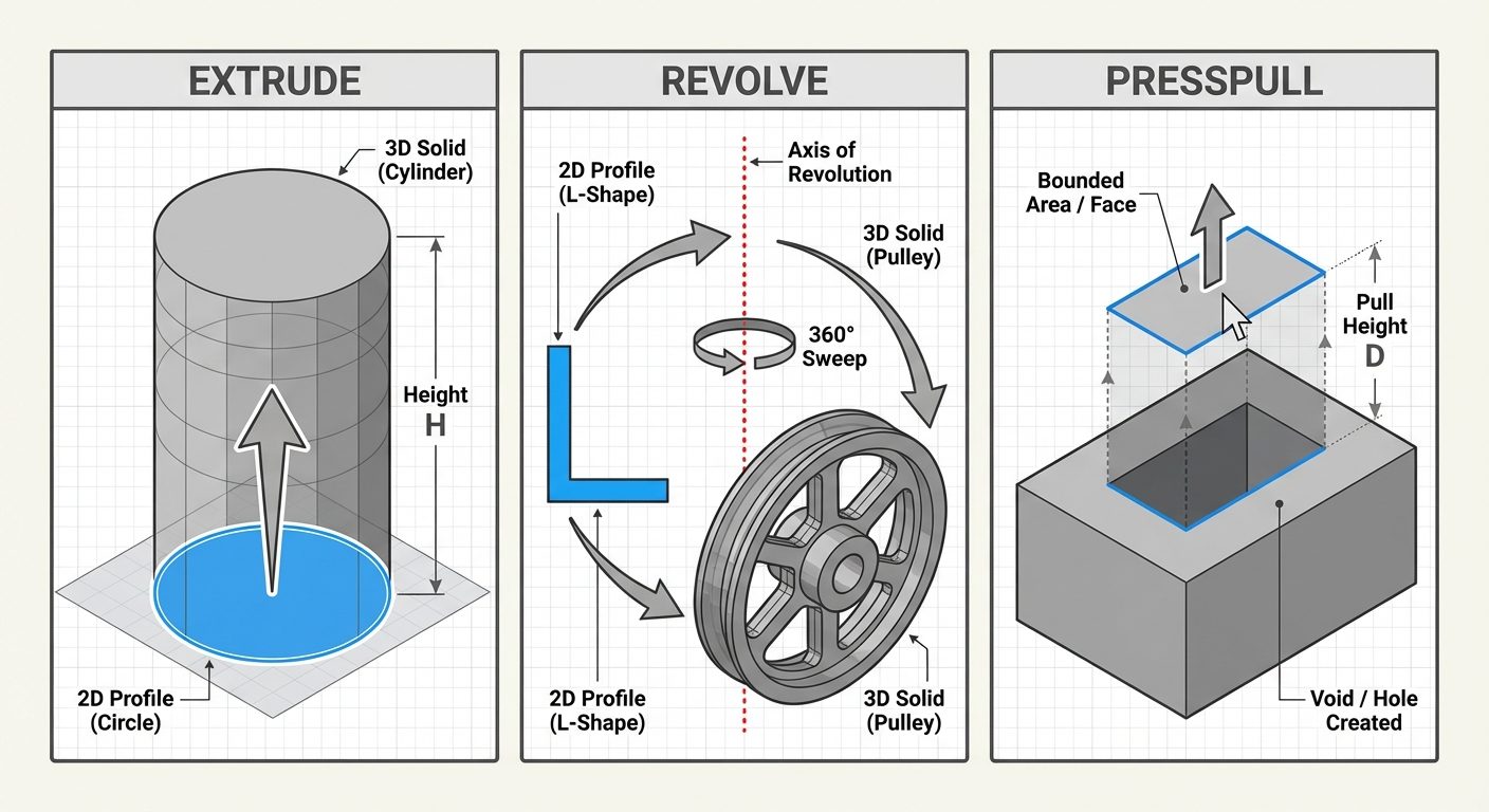
C. Extrude (EXTRUDE)
Converts 2D objects into 3D solids by stretching them along the Z-axis.
- Input: Must be a closed polyline, circle, or region.
- Procedure: Select object > Enter height > Enter taper angle (optional).
D. Revolve (REVOLVE)
Creates a solid by sweeping a 2D profile around an axis.
- Input: Closed profile and an axis line.
- Procedure: Select profile > Select axis > Enter angle of revolution (usually ).
- Application: Used for cylindrical objects like shafts, pulleys, and domes.
E. Presspull (PRESSPULL)
A dynamic modeling tool that creates 3D solids from bounded areas.
- Difference from Extrude: It does not require a polyline; it detects any enclosed area (boundary) bounded by coplanar lines.
- Function: Can add volume (pull) or subtract volume (push/void) from an existing solid.
7. Hands-on Practice on 3D Drawings
To master Unit 5, follow this workflow for a practice exercise (e.g., A Cylinder on a Cube):
-
Setup:
- Switch Workspace to "3D Modeling".
- Set View to "SE Isometric".
- Set Visual Style to "Shades of Grey".
-
Create the Base (Cube):
- Command:
BOX - Specify first corner:
0,0,0 - Select "Cube" option or input Length
100, Width100, Height100.
- Command:
-
Setup UCS for Top Face:
- Command:
UCS>Face> Select top face of cube. - Or enable
Dynamic UCS(F6).
- Command:
-
Create the Top Object (Cylinder):
- Command:
CYLINDER - Center point: Use Object Snap Tracking to find the midpoint of the cube's top face.
- Radius:
30 - Height:
60
- Command:
-
Union (Optional):
- If the objects should be one single solid, use
UNIONcommand and select both the cube and cylinder.
- If the objects should be one single solid, use
-
Dimensioning:
- Switch UCS back to WCS or align UCS with the face being dimensioned to add annotations.