Unit 6 - Notes
Unit 6: Development of Surfaces
1. Introduction to Development of Surfaces
Definition:
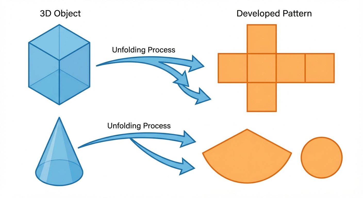
Development of surfaces is the process of unfolding or unrolling the surfaces of a 3D object (solid) into a 2D plane. The resulting 2D shape is called a "pattern" or a "development." When this pattern is cut out of a sheet of paper or metal and folded properly, it forms the original 3D object.
Key Concepts:
- Stretch-out Line: The full length or perimeter of the base of the object laid out in a straight line.
- True Length (TL): Development must always use the true dimensions of the edges. If an edge is inclined in an orthographic view, its true length must be determined before drawing the development.
- Application: Essential in sheet metal industries for fabricating ducts, pipes, hoppers, funnels, chimneys, and automobile body parts.
Principles:
- Every line on the development must represent the true length of the corresponding line on the surface.
- The opening/closing edge is usually the shortest edge to minimize welding/soldering.
2. Methods of Development
Different solids require different geometric methods to be developed effectively.
A. Parallel Line Method
- Usage: Used for Prisms and Cylinders.
- Principle: Since lateral edges are parallel to each other, the stretch-out line is drawn parallel to the base, and lateral edges are erected perpendicular to it.
- Formula: Length of development = Perimeter of the base.
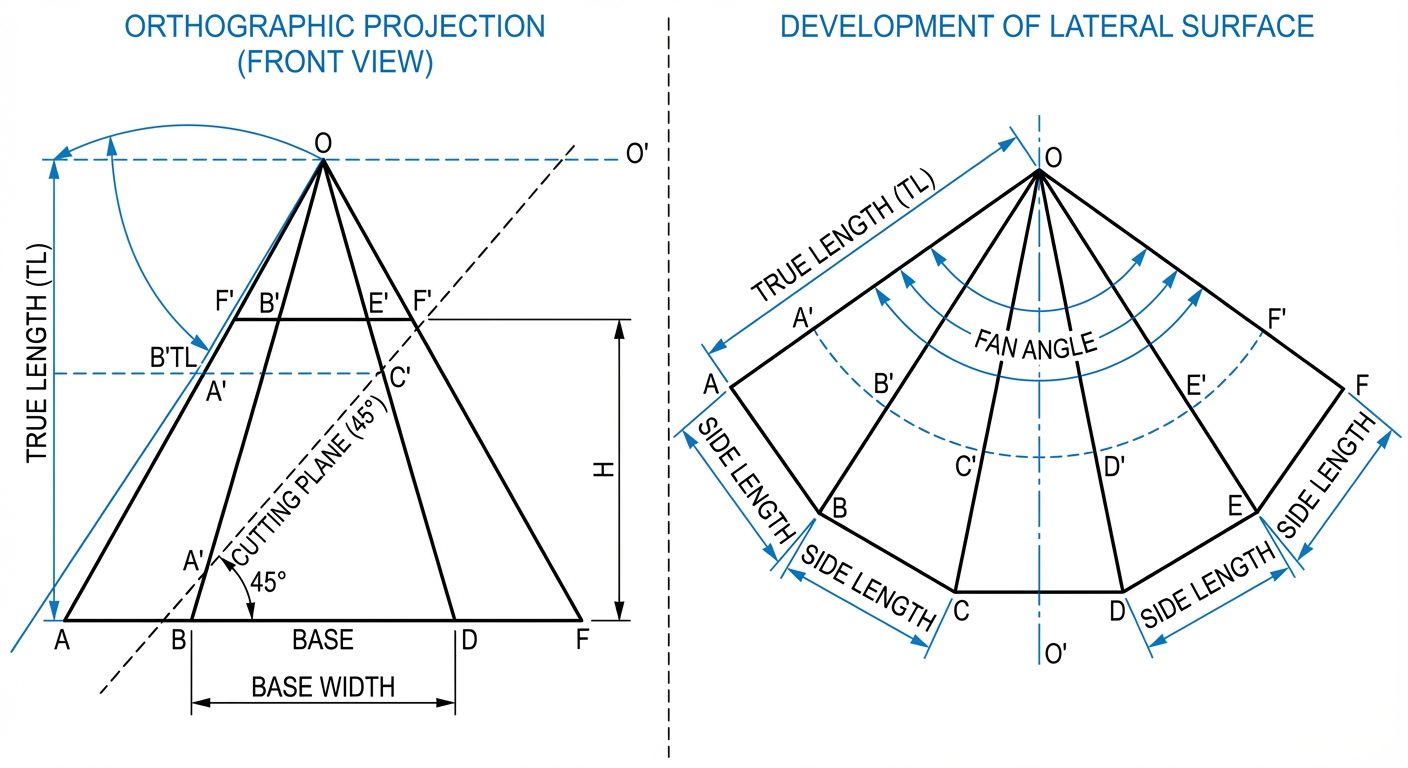
B. Radial Line Method
- Usage: Used for Pyramids and Cones.
- Principle: Since all lateral edges slant towards a single apex, the development is drawn as a sector of a circle with the Apex as the center and the slant edge (True Length) as the radius.
C. Triangulation Method
- Usage: Used for transition pieces (e.g., square to circular adapters) or irregular polyhedrons.
- Principle: The surface is divided into a series of triangles, the true sizes of which are found and laid out adjacent to each other.
3. Surface Development of Prisms and Pyramids
A. Regular and Truncated Prisms
Regular Prism: A solid with two congruent polygon bases parallel to each other, connected by rectangular lateral faces.
Truncated Prism: A prism cut by a plane inclined to the base. The development must account for the varying heights of the cut edges.
Procedure (Parallel Line Method):
- Draw the Top View and Front View of the prism.
- Draw the stretch-out line (length = Perimeter of base) horizontally aligned with the base of the Front View.
- Divide the stretch-out line into equal segments corresponding to the sides of the base.
- Erect vertical lines (generators) from these division points.
- If truncated: Project the intersection points of the cutting plane from the Front View horizontally to the corresponding vertical lines in the development.
- Join these points with straight lines.
B. Regular and Truncated Pyramids
Regular Pyramid: A solid with a polygon base and triangular faces meeting at a common apex.
Truncated Pyramid: A pyramid cut by a plane. The top portion is removed (frustum) or simply cut.
Procedure (Radial Line Method):
- Draw Orthographic views. Determine the True Length (TL) of the slant edge. Note: If the slant edge in the Front View is not parallel to the XY plane, rotate it to finding the TL.
- Draw an arc with the Apex as the center and radius = TL.
- Step off chord lengths on this arc equal to the side length of the base polygon.
- Join these points to the Apex to form the triangular faces.
- If truncated: Mark the cutting points on the True Length slant edge in the Front View. Transfer these distances to the corresponding radial lines in the development using concentric arcs.
4. AutoCAD Commands for 3D Modeling
Transitioning from 2D development to 3D modeling involves creating the solid object virtually.
A. Setting the Workspace
- Switch workspace from "Drafting & Annotation" to "3D Modeling".
- This activates the 3D ribbon containing Modeling, Solid Editing, and Visual Styles panels.
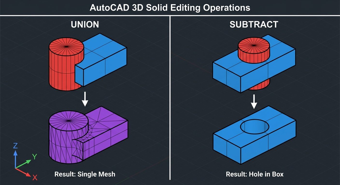
B. Boolean Operations (Solid Editing)
These commands allow the creation of complex solids by combining or cutting primitive shapes.
-
UNION (
UNIONorUNI):- Merges two or more separate 3D solids or regions into a single composite object.
- Steps: Type
UNI> Select Object 1 > Select Object 2 > Enter.
-
SUBTRACT (
SUBTRACTorSU):- Removes the volume of one solid from another (essential for truncated surfaces).
- Steps: Type
SU> Select the object to KEEP (Enter) > Select the object to REMOVE (Enter).
-
INTERSECT (
INTERSECTorIN):- Creates a solid from the overlapping volume of two or more solids.
C. 3D Navigation and Viewing
-
3D Orbit (
3DORBITor3DO):- Allows the user to rotate the view around the object freely in 3D space.
- Usage: Hold
Shift+Middle Mouse Wheelto orbit dynamically without typing the command.
-
Visual Styles (
VS):- Controls how the edges and faces of the 3D object are displayed.
- 2D Wireframe: Shows only boundaries/edges (fastest performance).
- Conceptual: Smooth shading with warm/cool colors (good for understanding form).
- Realistic: Applies materials and textures.
- Hidden: Wireframe but lines behind the object are hidden.
5. Hands-on Practice: 3D Drawings
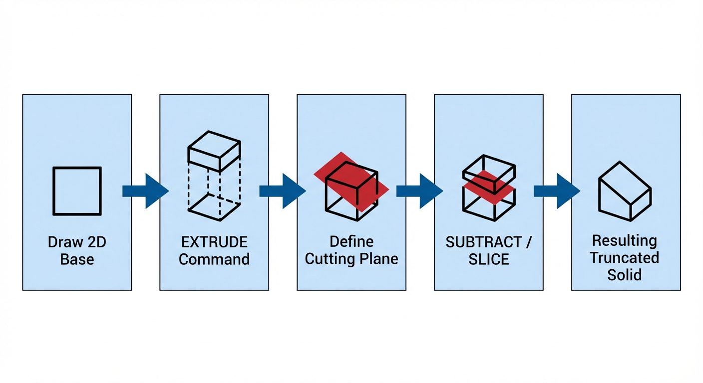
Exercise: Modeling a Truncated Square Prism
To visualize the solid before generating its development physically, follow this workflow in AutoCAD.
Step 1: Create the Base
- Set View to Top.
- Command:
REC(Rectangle). Draw a square (e.g., 50x50). - Command:
REGION. Select the square to convert lines into a surface region.
Step 2: Create the Solid (Extrusion)
- Set View to SE Isometric.
- Command:
EXT(Extrude). Select the region. - Specify height (e.g., 100). You now have a regular prism.
Step 3: Truncate the Solid (Slice or Subtract)
Method A: Using Slice
- Command:
SLICE. Select the prism. - Choose "3 points" option.
- Pick 3 points defining the cutting plane (e.g., two points on one face at different heights, one point on the back face).
- Select the side to keep.
Method B: Using Subtract (for complex cuts)
- Change UCS (User Coordinate System) to the Front face (
UCS>Face). - Draw a Polyline (
PL) representing the shape to be removed (a triangle wedge). EXTthe wedge so it passes through the prism.- Command:
SUBTRACT. Select Prism (Enter) > Select Wedge (Enter).
Step 4: Generating 2D Views from 3D Model
- Switch to Layout Tab.
- Command:
VIEWBASE. Select "From Model Space". - Place the Front, Top, and Isometric views.
- These views are linked to the 3D model and update automatically.