Practical 7
Practical 7: Project Areas
1. Aim/Objective
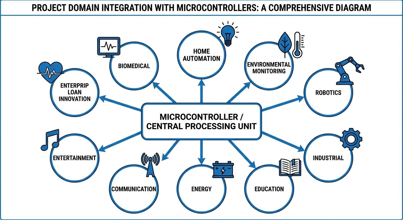
To explore broad application domains in Electrical and Electronics Engineering by designing and implementing prototype circuits for Home Automation and Environmental Monitoring, while theoretically analyzing system architectures for Robotics, Industrial, Education, Energy, Communication, Entertainment, and Biomedical applications.
2. Apparatus/Components Required
To cover the wide range of project areas, a modular microcontroller-based development kit is used along with specific sensors and actuators.
Hardware:
- Microcontroller Board: Arduino UNO (ATmega328P) or ESP32 (for IoT applications).
- Sensors:
- LDR (Light Dependent Resistor) – Home Automation
- DHT11/DHT22 (Temperature & Humidity Sensor) – Environmental Monitoring
- Ultrasonic Sensor (HC-SR04) – Robotics/Automation
- Actuators/Output:
- 5V Relay Module (Single Channel) – Industrial/Home Auto
- Servo Motor (SG90) – Robotics
- LEDs (Red, Green, Blue) and 330Ω Resistors.
- Piezo Buzzer – Entertainment/Alarms
- General:
- Breadboard (840 tie-points).
- Jumper Wires (Male-Male, Male-Female).
- Multimeter.
- USB Cable for programming.
- Software:
- Arduino IDE (Integrated Development Environment).
3. Theory
Electrical and electronics engineering projects generally fall into specific domains, each utilizing distinct sensors, control logic, and output mechanisms.
A. Core Project Domains
- Home Automation: Involves automatic control of lighting, climate, and appliances.
- Key Components: Relays, LDRs, PIR motion sensors, Wi-Fi modules.
- Environmental Monitoring: Tracking physical parameters like temperature, humidity, air quality (gas sensors), and pressure.
- Key Components: DHT11, MQ-series gas sensors, Barometers.
- Robotics & Automation: Systems capable of performing tasks automatically.
- Key Components: DC Motors, Servo motors, Ultrasonic obstacle sensors, Drivers (L293D).
- Industrial Applications: Focuses on process control, safety systems, and PLCs (Programmable Logic Controllers).
- Key Components: High-current relays, Inductive proximity sensors, Emergency stops.
- Energy & Power Systems: Management of power generation, battery charging, and load monitoring.
- Key Components: Voltage sensors, Current sensors (ACS712), Solar panels.
- Communication Systems: Data transmission between devices (Wired or Wireless).
- Key Components: Bluetooth (HC-05), RF modules (nRF24L01), ZigBee.
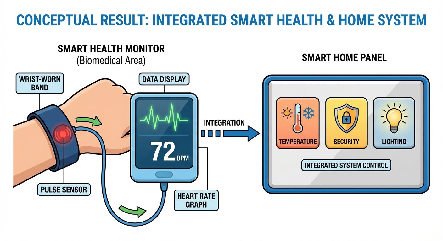
- Biomedical & Health: Monitoring physiological signals.
- Key Components: Pulse sensors, EMG sensors, Temperature probes.
B. Working Principle of Selected Prototypes
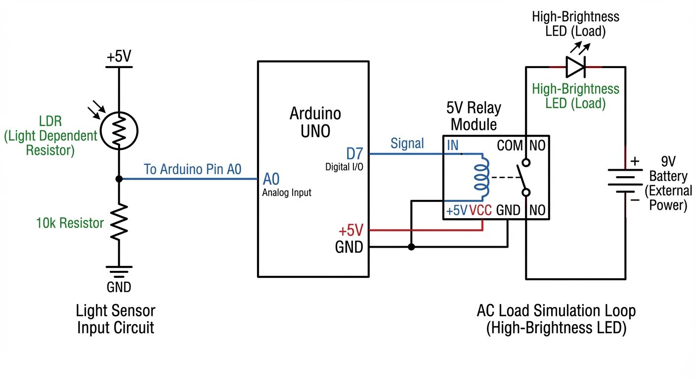
- Automatic Night Lamp (Home Automation): Uses a voltage divider circuit with an LDR. When light intensity drops, resistance increases, voltage at the analog pin changes, and the controller triggers a Relay to switch on an AC bulb (simulated by LED).
- Weather Station (Environmental Monitoring): The DHT11 sensor uses a capacitive humidity sensor and a thermistor to measure surrounding air. It sends a digital signal to the microcontroller.
4. Circuit Diagram / Setup
Setup A: Home Automation (Smart Light Control)
- Input: LDR connected in series with a 10kΩ resistor (Voltage Divider). Junction connected to Analog Pin A0.
- Output: Relay Module control pin connected to Digital Pin 7.
- Status: LED on Pin 13 indicates system status.
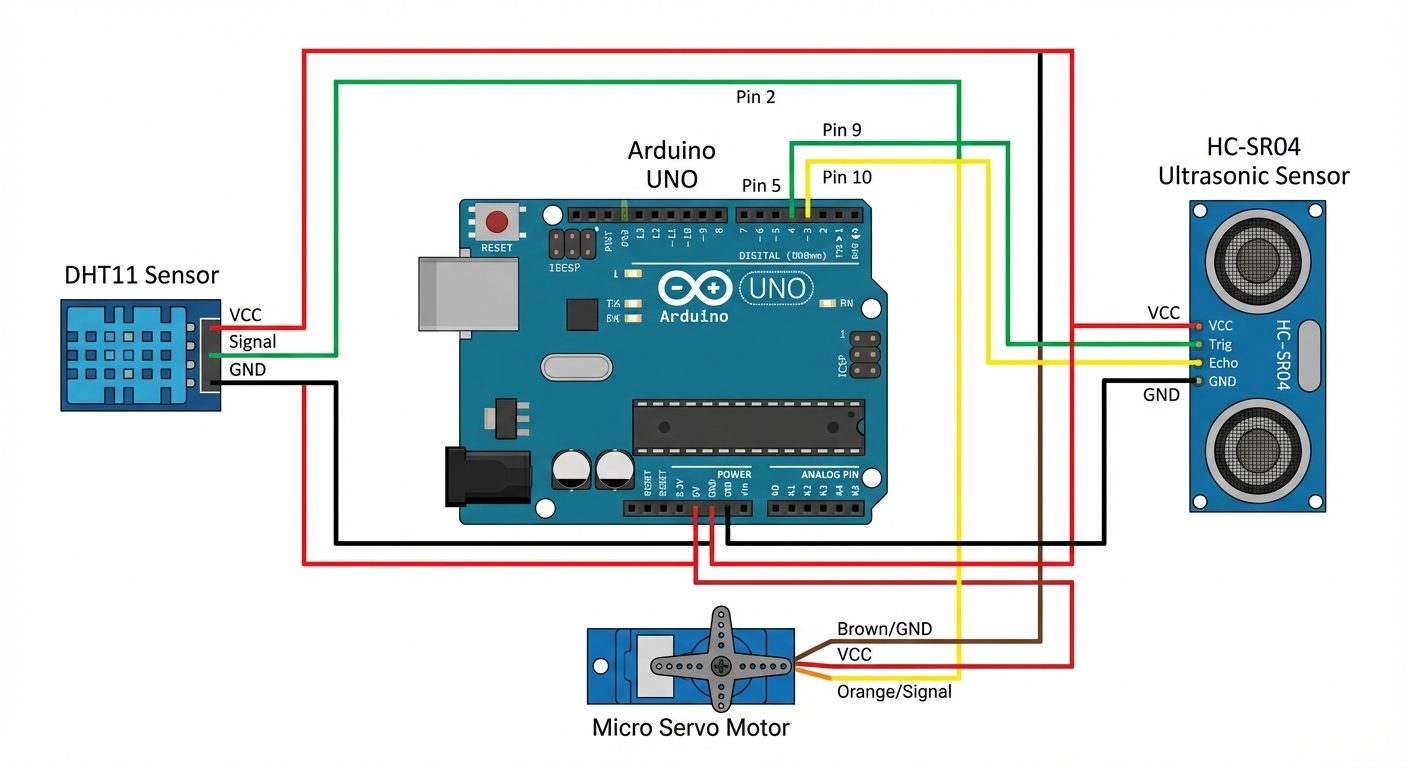
Setup B: Environmental & Robotics (Distance & Temp Monitor)
- Sensor 1: DHT11 Data pin to Digital Pin 2.
- Sensor 2: Ultrasonic HC-SR04 (Trig to Pin 9, Echo to Pin 10).
- Output: Servo Motor signal wire to Pin 5 (simulating a robotic arm movement or vent opening based on temperature).
5. Procedure
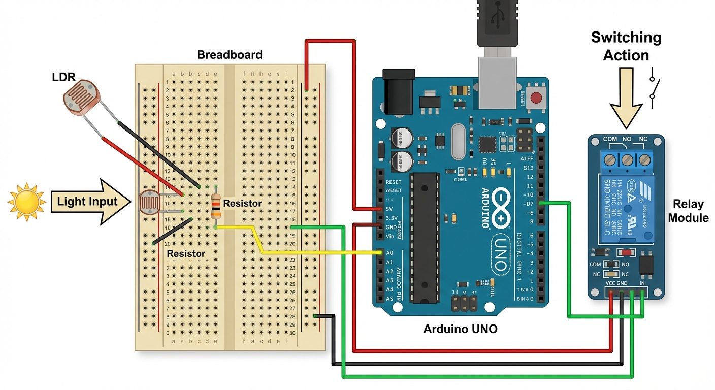
Part 1: Home Automation Prototype (Smart Lighting)
- Connect the Input: Place the LDR and a 10kΩ resistor in series on the breadboard. Connect +5V to the LDR side and GND to the resistor side. Connect the junction point to Arduino Pin A0.
- Connect the Output: Connect the VCC and GND of the Relay Module to the Arduino 5V and GND. Connect the Relay Input (IN) pin to Digital Pin 7.
- Load Connection: Connect an LED in the Normally Open (NO) path of the relay to visualize the switching action.
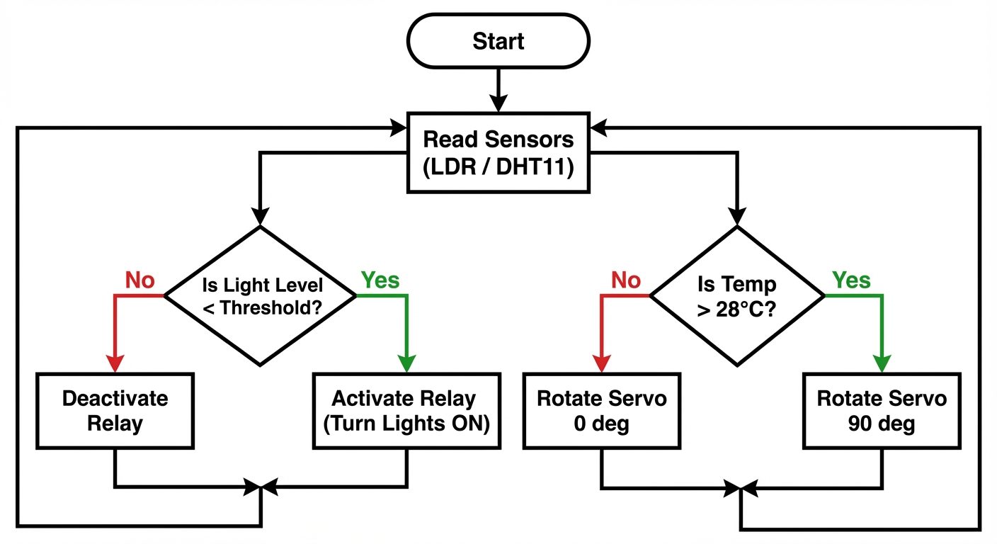
- Logic: Upload code that reads the analog value (0-1023). If the value drops below a threshold (e.g., < 300, representing darkness), turn Pin 7 HIGH (Relay ON). Otherwise, LOW.
Part 2: Environmental & Robotics Integration
- DHT11 Connection: Connect pin 1 to 5V, pin 4 to GND, and pin 2 to Digital Pin 2. (Use a 4.7kΩ pull-up resistor on pin 2 if using the raw sensor, or direct connect if using a module).
- Actuation: Connect the Servo motor signal to Pin 5.
- Logic: Upload code to read Temperature.
- If Temperature > 28°C, rotate Servo to 90° (Simulates opening a cooling vent/fan).
- If Temperature < 28°C, rotate Servo to 0° (Close vent).
Part 3: Conceptual Analysis (Lab Report Requirement)
For the domains not physically built (Biomedical, Communication, etc.), sketch a block diagram in the observation notebook using the components listed in the Theory section.
6. Observations & Readings
Observation Table 1: LDR Sensor (Home Automation)
| Condition | Analog Reading (0-1023) | Calculated Voltage (V) | Relay Status (ON/OFF) |
|---|---|---|---|
| Ambient Room Light | 750 (approx) | 3.66 V | OFF |
| Sensor Covered (Dark) | 150 (approx) | 0.73 V | ON |
| Flashlight applied | 950 (approx) | 4.64 V | OFF |
Sample Code Logic (Pseudo-code):
int sensorValue = analogRead(A0);
if (sensorValue < 300) {
  digitalWrite(7, HIGH); // Turn Relay ON
} else {
  digitalWrite(7, LOW);  // Turn Relay OFF
}
Observation Table 2: Environmental & Robotics Response
| Time (t) | Temperature (°C) | Condition Defined | Servo Angle (Output) |
|---|---|---|---|
| t = 0 min | 24°C | Normal | 0° |
| t = 2 min | 29°C | Overheating (Simulated) | 90° |
| t = 4 min | 25°C | Cooled Down | 0° |
7. Calculations
1. Voltage Divider Calculation for LDR:
Where:
- If in dark :
(This matches the low analog reading observed in darkness).
2. Relay Driver Current:
Typical 5V relay coil resistance .
Note: This current is safe for the USB supply but requires a transistor driver (built into the module) as the Arduino pin limit is 40mA.
8. Result
- The Home Automation prototype successfully detected light variations; the relay switched ON the load when light intensity fell below the threshold (Analog value < 300).
- The Environmental/Robotics system successfully monitored temperature and actuated the servo motor automatically when the temperature exceeded the setpoint of 28°C.
- The diverse project areas were analyzed, demonstrating how basic components (sensors, controllers, actuators) are common across domains like Robotics, Biomedical, and Industrial automation.
9. Viva Questions
Q1: What is the main difference between Home Automation and Industrial Automation?
Ans: Home automation focuses on comfort, energy saving, and convenience using lower power devices (Wi-Fi/Bluetooth). Industrial automation focuses on precision, reliability, safety, and high-speed production using PLCs, SCADA, and robust protocols like Modbus.
Q2: Which sensor would you use for a collision-avoidance robot?
Ans: An Ultrasonic sensor (HC-SR04) or an Infrared (IR) proximity sensor is commonly used to detect distance and obstacles.
Q3: Explain the role of a Relay in these project areas.
Ans: A Relay acts as an electromagnetic switch that allows a low-power microcontroller (5V DC) to control high-power devices (like 230V AC bulbs or motors) while providing electrical isolation between the two circuits.
Q4: In an environmental monitoring system, how does a DHT11 sensor transfer data?
Ans: It uses a single-wire digital protocol. The microcontroller sends a start signal, and the sensor responds with a pulse train containing 40 bits of data (Humidity integer, decimal, Temp integer, decimal, and checksum).
Q5: For a biomedical project measuring heart rate, what type of sensing principle is used?
Ans: Photoplethysmography (PPG). It uses a light source (LED) and a photodetector to measure changes in light absorption caused by the varying volume of blood in the tissue during a heartbeat.
Q6: What is the function of the Servo Motor in the experiment?
Ans: The servo motor acts as an actuator that provides precise angular positioning (0 to 180 degrees), used here to simulate opening/closing a vent or moving a robotic arm.
Q7: How would you add "Communication" capabilities to the existing Home Automation setup?
Ans: By interfacing a Wi-Fi module (like ESP8266) or a Bluetooth module (HC-05), allowing the system to send sensor data to a smartphone or receive control commands remotely.