Unit 2 - Notes
Unit 2: Introduction of Arduino and Sensors
1. Analog and Digital Signals
Understanding the difference between analog and digital signals is fundamental to interfacing sensors with microcontrollers like Arduino.
Analog Signals
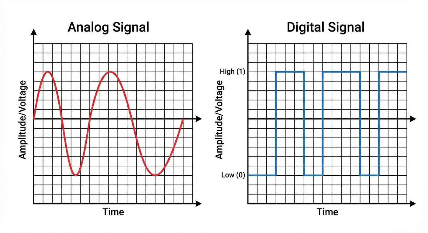
An analog signal is a continuous signal that represents physical measurements. It can take on any value within a given range.
- Characteristics: Continuous, smooth, and time-varying.
- Representation: Sine waves.
- Examples: Temperature, sound, pressure, light intensity, voltage from a potentiometer (0V to 5V).
- Arduino Interface: The Arduino UNO uses the ADC (Analog-to-Digital Converter) on pins A0–A5 to read these signals, converting a 0–5V voltage into an integer value between 0 and 1023 (10-bit resolution).
Digital Signals
A digital signal is a discrete signal that carries data in the form of binary numbers. It has only two distinct states.
- Characteristics: Discrete, non-continuous stepping.
- States: High (Logic 1 / 5V) or Low (Logic 0 / 0V).
- Representation: Square waves.
- Examples: Switches (On/Off), LED status, button presses.
- Arduino Interface: Digital pins (0–13) read these as
HIGHorLOW.
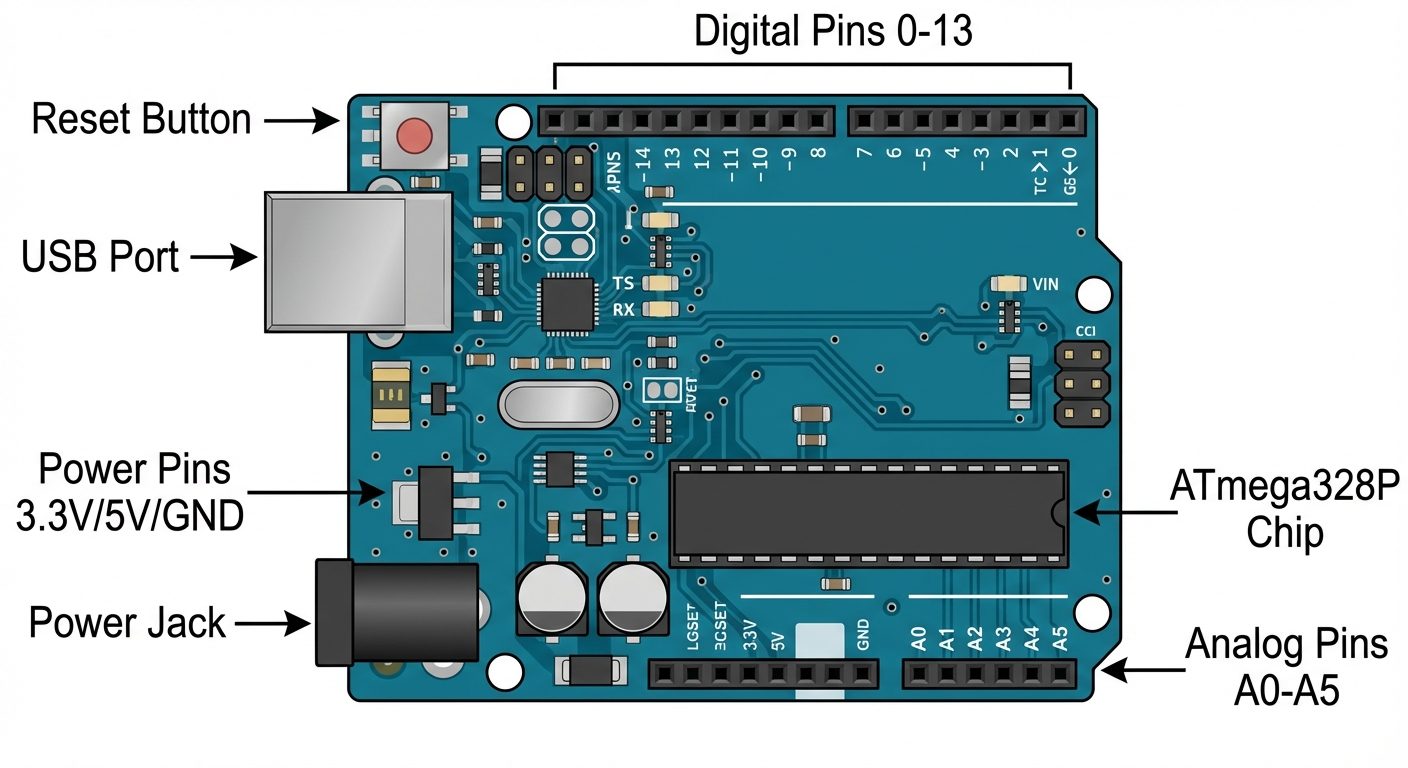
2. Arduino Board: Architecture and Pin Configuration
The Arduino UNO is an open-source microcontroller board based on the Microchip ATmega328P. It is the most standard board for beginners.
Key Specifications
- Microcontroller: ATmega328P
- Operating Voltage: 5V
- Input Voltage (recommended): 7–12V
- Clock Speed: 16 MHz
Pin Configuration and Description
1. Power Pins
- Vin: Input voltage to the Arduino when using an external power source (like a 9V battery).
- 5V: Outputs a regulated 5V from the regulator on the board. Used to power sensors.
- 3.3V: Outputs a regulated 3.3V. Maximum current draw is 50 mA.
- GND: Ground pins. There are several GND pins on the board; they must be connected to the circuit ground.
- RESET: Bringing this line LOW resets the microcontroller.
2. Analog Input Pins (A0 – A5)
- Used to measure analog voltages (0V–5V).
- Internally connected to a 10-bit Analog-to-Digital Converter (ADC).
- Can also be used as standard digital I/O pins if required.
3. Digital I/O Pins (0 – 13)
- Can be configured as input (reading sensors) or output (controlling LEDs/motors) using
pinMode(). - Serial Communication (Pins 0 & 1): Pin 0 (RX) is for receiving data; Pin 1 (TX) is for transmitting data. Avoid using these if communicating with the computer via USB.
- PWM Pins (~): Pins marked with a tilde (3, 5, 6, 9, 10, 11). These provide 8-bit Pulse Width Modulation output (simulated analog output) using
analogWrite(). - Built-in LED: Connected to Pin 13.
4. Other Components
- USB Port: Used for powering the board and uploading code from the computer.
- DC Power Jack: Used to power the board via a wall adapter.
- ICSP Header: In-Circuit Serial Programming (for advanced users to program the chip directly).
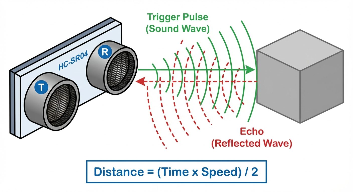
3. Ultrasonic Sensor (HC-SR04)
The HC-SR04 is a distance measuring sensor that uses ultrasonic sound waves (sonar) to determine the distance to an object.
Basic Principle
The sensor works on the principle of Echolocation (similar to bats or dolphins).
- Transmission: The sensor emits a high-frequency sound pulse (40 kHz) from the Transmitter.
- Reflection: If the sound wave hits an obstacle, it bounces back (echoes).
- Reception: The Receiver detects the returning echo.
- Calculation: The time duration between transmission and reception is measured.
Pin Configuration
- VCC: +5V Supply.
- Trig (Trigger): Input pin. A 10µs HIGH pulse is sent here to initiate the measurement.
- Echo: Output pin. It goes HIGH for a duration equal to the time taken for the sound to return.
- GND: Ground.
Distance Formula
Since sound travels to the object and back, the distance is calculated as:
Speed of sound is approximately 343 m/s (or 0.0343 cm/µs).
4. Temperature and Humidity Sensor (DHT11/DHT22)
The DHT sensors are cost-effective digital sensors for measuring ambient temperature and humidity.
Comparison: DHT11 vs. DHT22
- DHT11: Blue casing. Measures 0-50°C (±2°C accuracy) and 20-80% humidity. Slower sampling rate (1 Hz).
- DHT22: White casing. Measures -40 to 80°C (±0.5°C accuracy) and 0-100% humidity. More precise but slightly more expensive.
Working Principle
- Humidity Sensing: Uses a capacitive humidity sensor (a polymer sandwich that changes capacitance based on moisture absorption).
- Temperature Sensing: Uses a thermistor (NTC) to measure temperature.
- Data Output: Inside the casing, a small chip converts the analog readings from the capacitor and thermistor into a digital serial signal that is sent to the Arduino via a single data pin.
Pinout
- VCC: 3.3V – 5V Power.
- Data: Digital signal output (requires a pull-up resistor).
- NC: Not Connected.
- GND: Ground.
5. Light Dependent Resistor (LDR)
An LDR, or Photoresistor, is a variable resistor controlled by light intensity.
Working Principle
- Photoconductivity: It is made of high-resistance semiconductor material (Cadmium Sulfide).
- Darkness: In the dark, the resistance is very high (Mega-Ohms range).
- Light: When photons hit the surface, electrons are excited, conductivity increases, and resistance drops drastically (a few hundred Ohms).
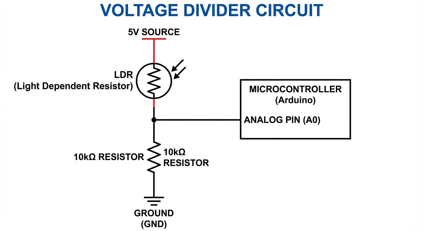
Circuit Connection (Voltage Divider)
Since Arduino measures voltage, not resistance, the LDR must be used in a Voltage Divider Configuration.
- Connect the LDR in series with a fixed resistor (e.g., 10kΩ).
- Connect the junction point between the LDR and the resistor to an Arduino Analog Pin (e.g., A0).
- As light changes, the resistance of the LDR changes, altering the voltage at the junction point.
6. IR (Infrared) Sensor
IR sensors are widely used for obstacle detection, line-following robots, and proximity sensing.
Components
An IR sensor module consists of two main optical components:
- IR Transmitter (IR LED): Emits infrared light (invisible to the human eye).
- IR Receiver (Photodiode): Detects infrared light.
Working Principle
The sensor operates on light reflection.
- The IR LED continuously emits IR light.
- If an object is present: The IR light hits the object and reflects back to the photodiode. The receiver detects this and the module output goes LOW (Logic 0).
- If no object / Black surface: The IR light either goes on forever (no obstacle) or is absorbed by the black surface (no reflection). The receiver detects nothing, and the output remains HIGH (Logic 1).
Note: The sensitivity (distance) is usually adjustable via an onboard potentiometer.
Pin Configuration
- VCC: 5V Power.
- GND: Ground.
- OUT: Digital Output (High/Low) connected to Arduino digital pin.