ETE Practice Questions
First Angle Projection:
- The object is placed in the First Quadrant (between the observer and the plane of projection).
- The object is assumed to be opaque.
- Top View is drawn below the Front View.
- Symbol: Two concentric circles with a trapezoid on the left.
Third Angle Projection:
- The object is placed in the Third Quadrant (the plane of projection is between the observer and the object).
- The plane of projection is assumed to be transparent.
- Top View is drawn above the Front View.
- Symbol: Two concentric circles with a trapezoid on the right.
Definition:
Additive Manufacturing (AM), often synonymous with 3D printing, is a process of joining materials to make objects from 3D model data, usually layer upon layer, as opposed to subtractive manufacturing methodologies.
Difference from Traditional Machining:
- Additive: Builds parts by adding material layer by layer (e.g., FDM, SLS).
- Subtractive (Traditional): Creates parts by removing material from a solid block (e.g., Milling, Turning, Drilling).
Definition:
STL (Stereolithography or Standard Triangle Language) is the standard file format used for 3D printing and Rapid Prototyping.
Significance:
- It approximates the surface of a 3D CAD model using a mesh of triangles.
- It removes attributes like color and texture, focusing solely on the geometry required for slicing software to generate toolpaths (G-code) for the printer.
- Concept Modeling: Creating physical models to visualize design ideas early in the development process.
- Functional Testing: Creating prototypes to test fit, form, and function (aerodynamics, fluid flow, assembly fit).
- Medical Applications: Custom implants, prosthetics, and anatomical models for surgical planning.
- Tooling: Rapid tooling for injection molds or casting patterns.
Calculations:
- R.F. (Representative Fraction): 1/40
- Maximum Length: 6 meters = 600 cm
- Length of Scale (L.O.S): R.F. × Max Length = (1/40) × 600 cm = 15 cm
Construction Steps:
- Draw a line 15 cm long and divide it into 6 equal parts. Each part represents 1 meter.
- Subdivide the first part (0 to left) into 10 equal divisions to represent Decimeters.
- Draw vertical lines upward and construct the diagonal scale structure to represent Centimeters on the vertical axis (10 divisions).
- To mark 4.76 m: Move to 4 meters on the main scale, 7 decimeters on the subdivision, and move up the diagonal to the 6th centimeter line.
Analysis:
- True Length (TL): 50 mm
- Inclination to HP (): 30°
- Inclination to VP (): 0° (Parallel to VP)
- Position of A: 20 mm above XY, 25 mm below XY (in Top View).
Drawing Steps:
- Draw the XY reference line.
- Mark a' (Front View of A) 20 mm above XY and a (Top View of A) 25 mm below XY.
- Front View: Since the line is parallel to VP, the Front View shows the True Length and True Inclination. Draw a line from a' at 30° to XY with a length of 50 mm to find point b'.
- Top View: Since the line is inclined to HP but parallel to VP, the Top View will be shorter (apparent length). Project a vertical line down from b'.
- Draw a line from a parallel to the XY line until it intersects the projector from b'. Mark this intersection as b.
- Join a'b' (Front View) and ab (Top View).
Process Description:
Fused Deposition Modeling (FDM) is an extrusion-based 3D printing technology.
- Material: It uses a thermoplastic filament (PLA, ABS, PETG) wound on a spool.
- Extrusion: The filament is fed through a heated nozzle where it melts.
- Deposition: The nozzle moves in X and Y coordinates, depositing the molten material onto a build platform layer by layer.
- Solidification: The material cools and solidifies almost immediately after extrusion, bonding with the previous layer.
Advantages:
- Cost-effective: Machines and materials are relatively cheap.
- Variety of Materials: Supports high-strength engineering plastics.
- Clean Process: No powders or liquid resins, suitable for office environments.
Limitations:
- Anisotropy: Parts are weaker in the Z-axis (between layers).
- Surface Finish: Visible layer lines often require post-processing.
- Resolution: generally lower detail compared to SLA or SLS.
The generic process chain consists of the following 5 steps:
- 3D Modeling (CAD): Creating a digital design of the object using CAD software (SolidWorks, AutoCAD, Fusion 360).
- Data Conversion (STL): Converting the CAD file into .STL format, which triangulates the surface geometry.
- Checking and Preparing: Using slicing software to check for file errors, orient the part, generate support structures, and slice the model into layers (generating G-code).
- Building (Printing): The machine reads the G-code and builds the part layer-by-layer using the specific technology (FDM, SLA, etc.).
- Post-Processing: Removing the part from the machine, cleaning off support structures, curing (if resin), and surface finishing (sanding/painting).
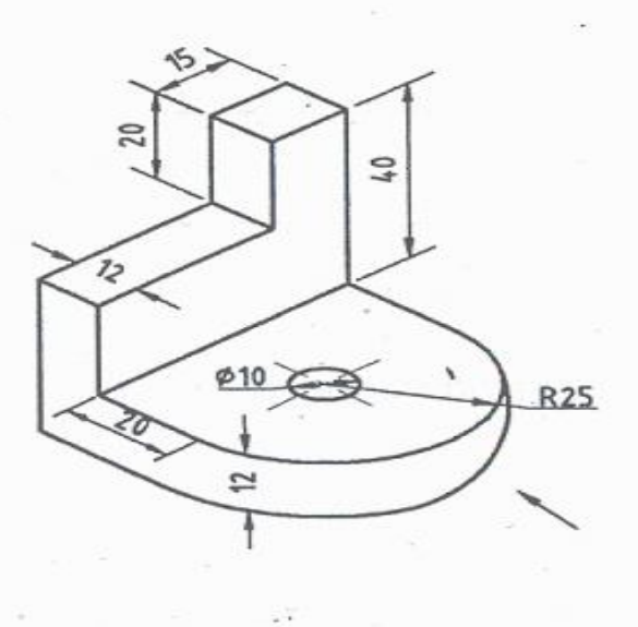
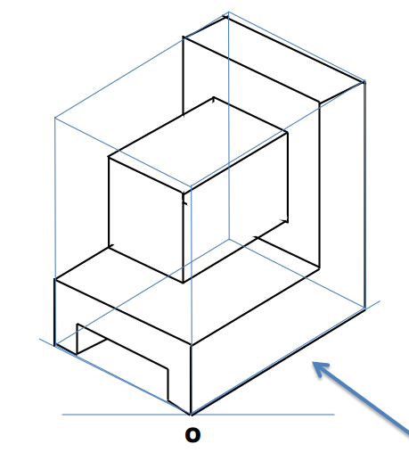
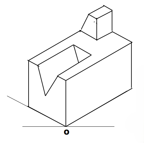
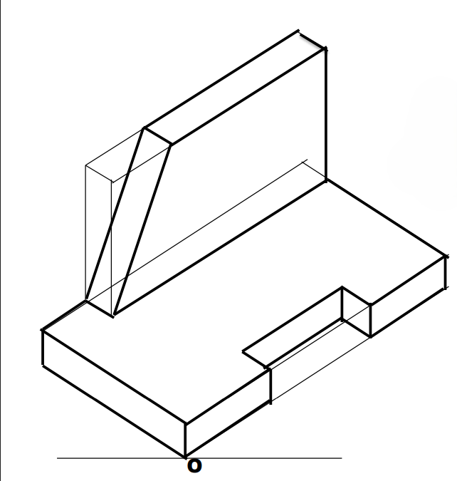
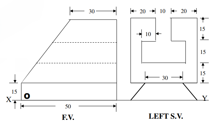
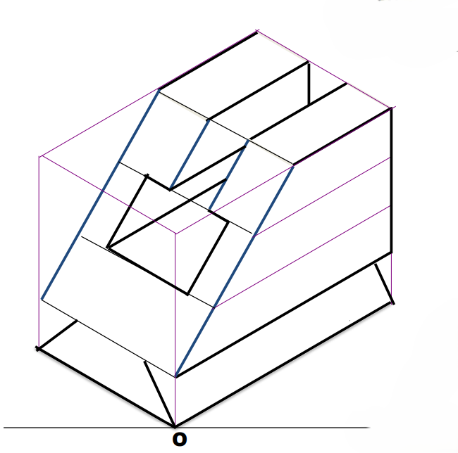
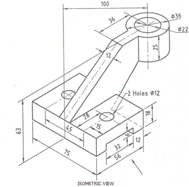
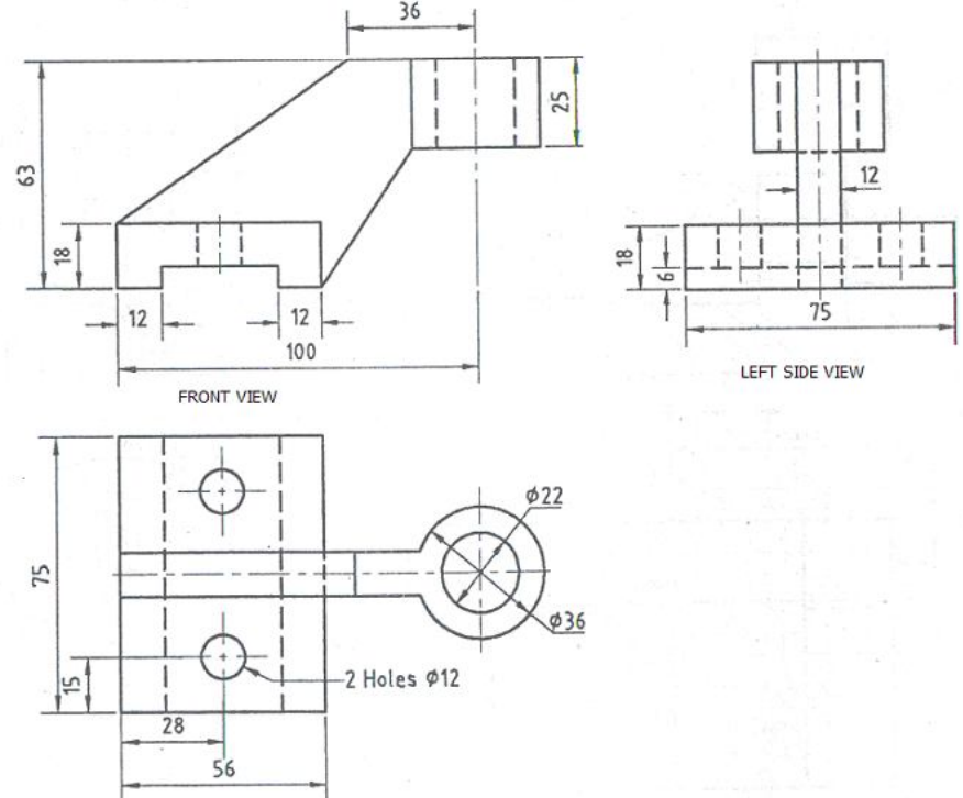
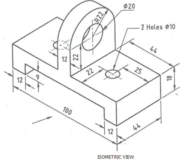
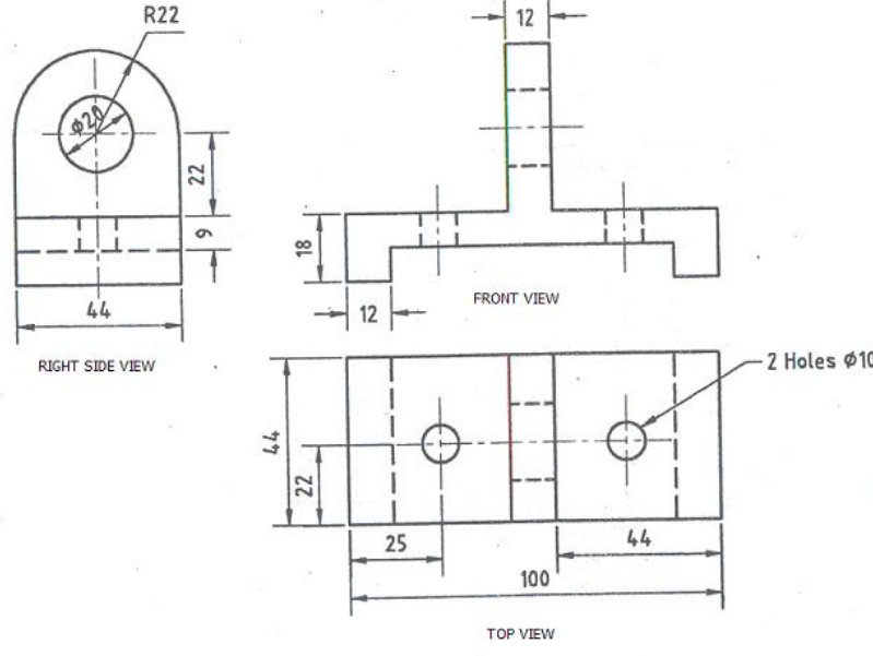
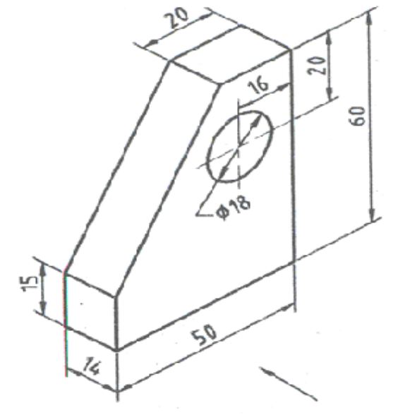
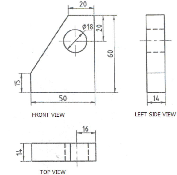
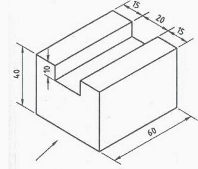
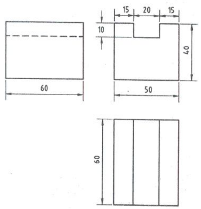
(i) Front View looking in the direction of arrow X.
(ii) Top View.
(iii) Left Side View.
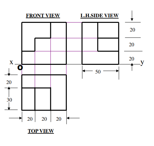
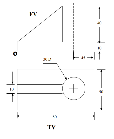
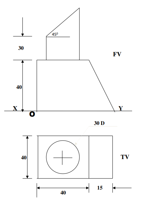
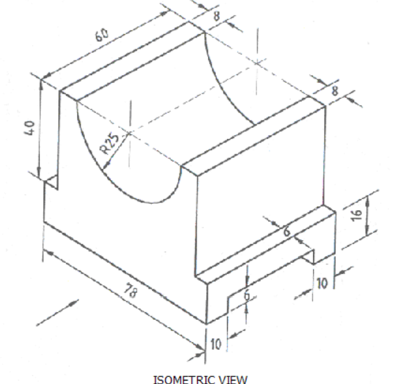
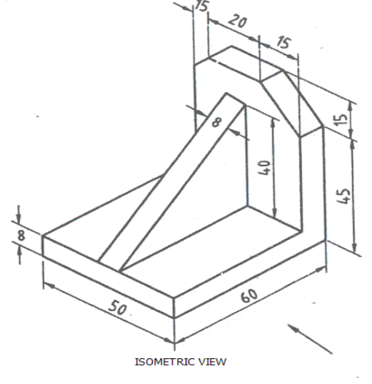
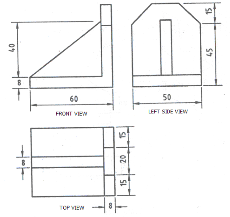
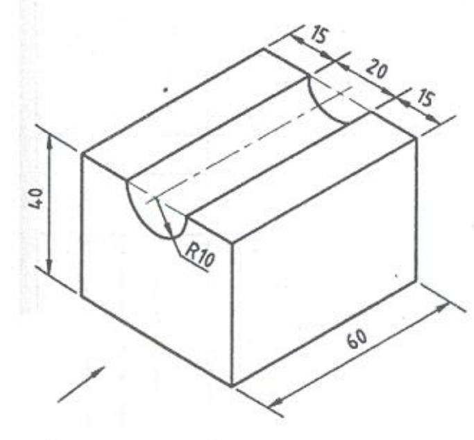
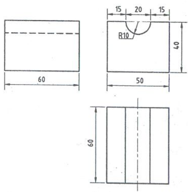
(i) Front View looking in the direction of arrow X.
(ii) Top View.
(iii) Left Side View.

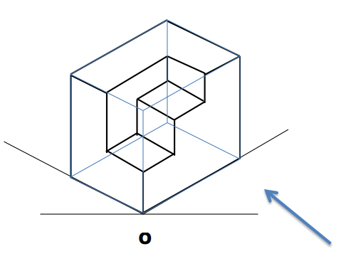
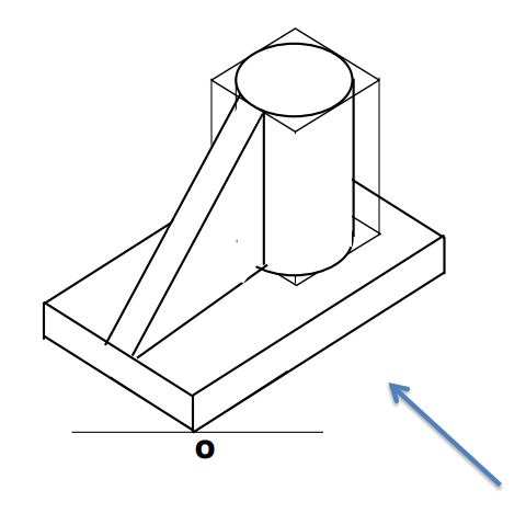
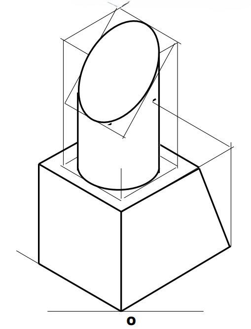
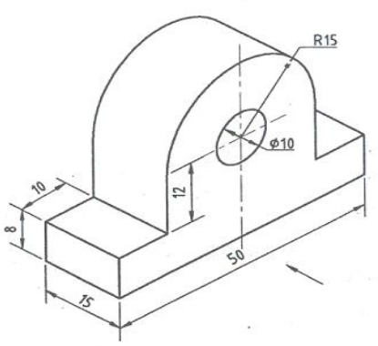
(i) Front View looking in the direction of arrow X.
(ii) Top View.
(iii) Left Side View.
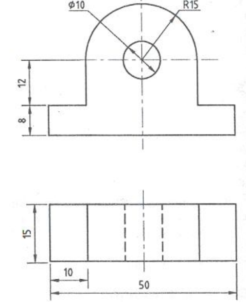
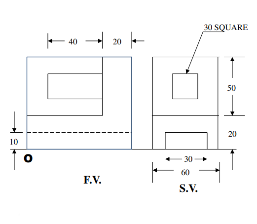
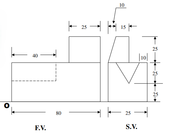
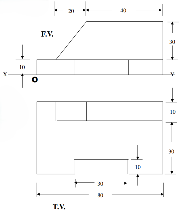
(i) Front View looking in the direction of arrow X.
(ii) Top View.
(iii) Left Side View.
(i) Front View looking in the direction of arrow X.
(ii) Top View.
(iii) Left Side View.
(i) Front View looking in the direction of arrow X.
(ii) Top View.
(iii) Left Side View.
(i) Front View looking in the direction of arrow X.
(ii) Top View.
(iii) Left Side View.
(i) Front View looking in the direction of arrow X.
(ii) Top View.
(iii) Left Side View.
(i) Front View looking in the direction of arrow X.
(ii) Top View.
(iii) Left Side View.